Method for Detecting the Presence of a Target Analyte in a Test Spot

a target analyte and test spot technology, applied in colloidal chemistry, instruments, biomass after-treatment, etc., can solve problems such as image distortion of acquired imag

Inactive Publication Date: 2007-02-22
NANOSPHERE INC
View PDF17 Cites 13 Cited by
  • Summary
  • Abstract
  • Description
  • Claims
  • Application Information

AI Technical Summary

Benefits of technology

[0017] Thus, an advantage of the present invention to provide an imaging system within a compact housing.
[0018] Another advantage of the present invention to avoid the necessity of using complex motorized systems to move the camera across the substrate.
[0019] Still another advantage of the present invention is the ability to detect spots and / or wells on the substrate without expensive or complicated implementations.

Problems solved by technology

Due to this close placement, the acquired image is subject to distortion, particularly at the edges of the acquired image.

Method used


Image

  • Method for Detecting the Presence of a Target Analyte in a Test Spot
  • Method for Detecting the Presence of a Target Analyte in a Test Spot
  • Method for Detecting the Presence of a Target Analyte in a Test Spot

Examples


Embodiment Construction

)

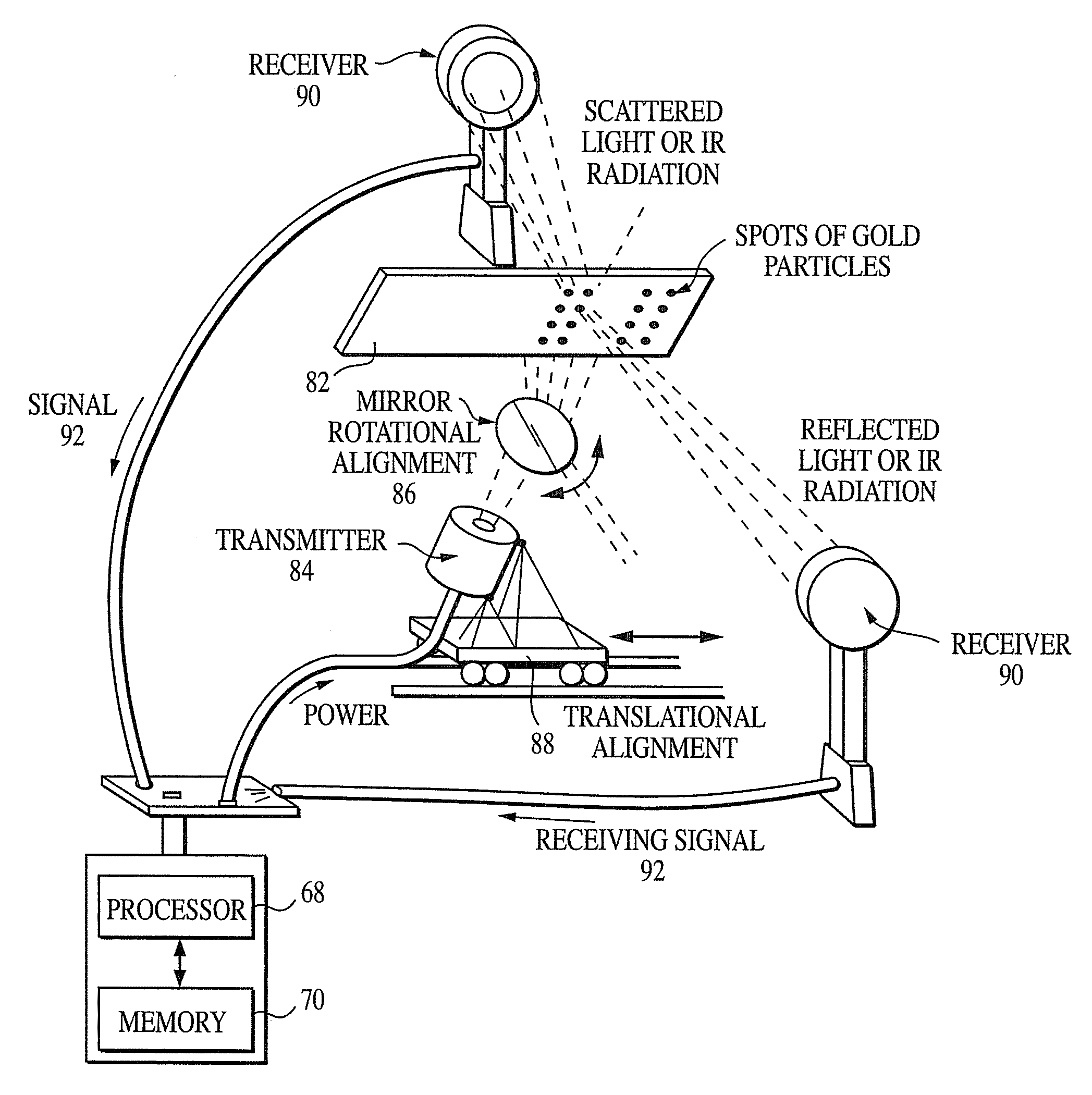
[0043] The method and apparatus of the present invention relates to detection of metallic nanoparticles. In a preferred embodiment, the invention provides for methods and apparatuses for detection of gold colloid particles and for accurate reporting to the operator.

[0044] The examples set forth herein relate to an imaging system and method for detection of nanoparticles and in particular metallic nanoparticles. In a preferred embodiment, the nanoparticles are gold nanoparticles (either entirely composed of gold or at least a portion (such as the exterior shell) composed of gold) and amplified with silver or gold deposited post-hybridization on to the gold nanoparticles. The present invention may also be applied to other applications including, without limitation, detection of gold nanoparticles without silver or gold deposition.

[0045] As discussed in the background of the invention, there are several problems when detecting nanoparticles on a substrate including, for example: lar...


PUM

PropertyMeasurementUnit
diameteraaaaaaaaaa
focal lengthaaaaaaaaaa
distanceaaaaaaaaaa

Abstract

An apparatus and method for imaging metallic nanoparticles is provided. Preferably, the invention provides for an apparatus and method for detection of gold colloid particles and for accurate reporting to the operator. The apparatus includes a substrate holder for holding the substrate, a processor and memory device, an imaging module, an illumination module, a power module, an input module, and an output module. The apparatus may have a stationary substrate holder and imaging module which are proximate to one another. The apparatus provided for a compact sized system without the need for complex motorized devices to move the camera across the substrate. Further, the apparatus and method provide for automatic detection of the spots / wells on the substrate, automatic quantification of the spots on the substrate, and automatic interpretation of the spots based on decision statistics.

Description

REFERENCE TO RELATED APPLICATIONS [0001] The current patent application claims priority to U.S. Patent Application Ser. No. 60 / 310,102 filed on Aug. 3, 2001 and entitled “Nanoparticle Imaging System and Method.” This application incorporates by reference U.S. Patent Application Ser. No. 60 / 310,102 in its entirety. The current patent application claims priority to U.S. Patent Application Ser. No. 60 / 366,732 filed on Mar. 22, 2002 and entitled “Method and System for Detecting Nanoparticles.” This application incorporates by reference U.S. Patent Application Ser. No. 60 / 366,732 in its entirety.FIELD OF THE INVENTION [0002] This present invention relates to detection of metallic nanoparticles. More specifically, the invention provides for methods and apparatuses for detection of gold colloid particles and for accurate reporting to the operator. BACKGROUND OF THE INVENTION [0003] Sequence-selective DNA detection has become increasingly important as scientists unravel the genetic basis of...

Claims


Application Information

Patent Timeline
Patent Type & Authority Applications(United States)
IPC IPC(8): G06K9/00G01N33/553B01J13/00B82B1/00C12M1/34C12Q1/68G01N21/25G01N21/27G01N21/75
CPCG01N21/253G01N33/54346
Inventor CORK, WILLIAMPATNO, TIMWEBER, MARKMORROW, DAVEBUCKINGHAM, WESLEY
Owner NANOSPHERE INC
Why Eureka
Try Eureka