Luminescent coating

Inactive Publication Date: 2007-02-22
LUMINOUS TECH
View PDF6 Cites 20 Cited by
  • Summary
  • Abstract
  • Description
  • Claims
  • Application Information

AI Technical Summary

Benefits of technology

[0016] The inert inorganic visual indicators of the present invention provide for a long life so that the coating may be easily inspected with a hand held UV light periodically after initial applications. The optical additives also provide a visua

Problems solved by technology

Moreover, subsequent coating damage caused by heat, abrasion, climate, corrosion and impacts must be taken into account when conducting inspections of such coatings.
For many applications, damage due to corrosion and impacts is often difficult to detect.
This is especially problematic on surfaces that are difficult to access with detection equipment.
The inspection survey of coatings on aircraft, seagoing vessels, underwater sections of offshore drilling rigs, production platforms as well as land installations such as oil and chemical storage tanks, reaction vessels and industrial plants, rail tank cars and similar structures is time consuming and therefore, costly.
Such time consuming inspections require skilled manpower and cause down time for the equipment being inspected.
Due to the complicated structure of some of the equipment, it may be difficult to carry out an accurate survey of all the parts of these structures wi

Method used


Image

  • Luminescent coating
  • Luminescent coating
  • Luminescent coating

Examples


Example

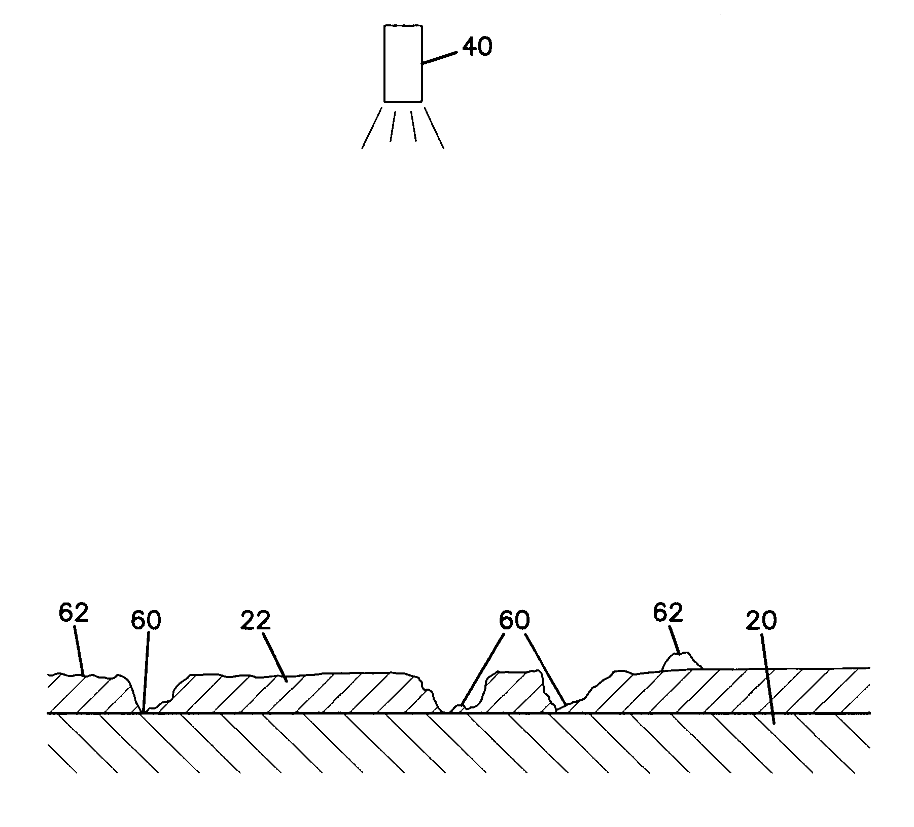
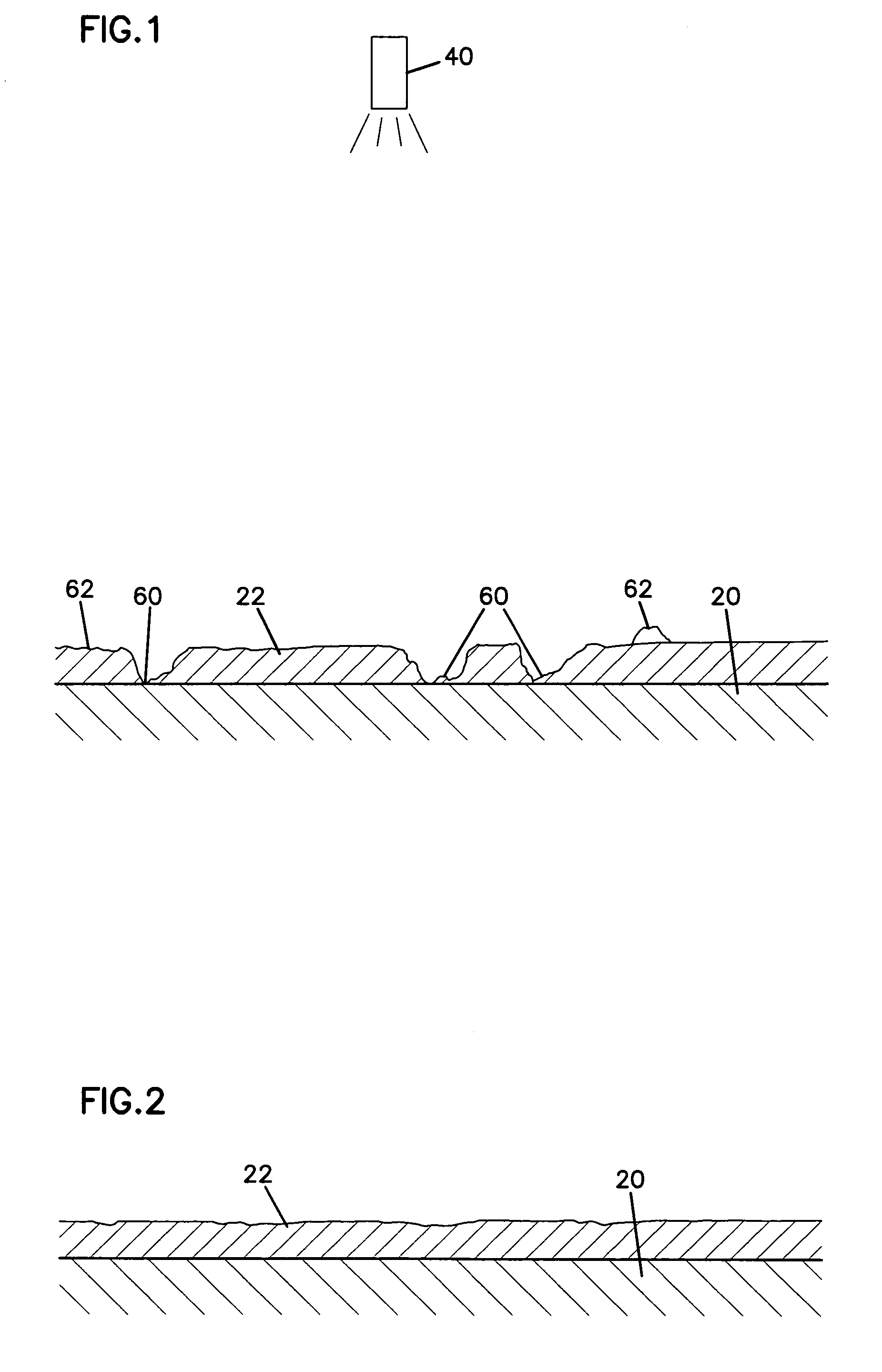
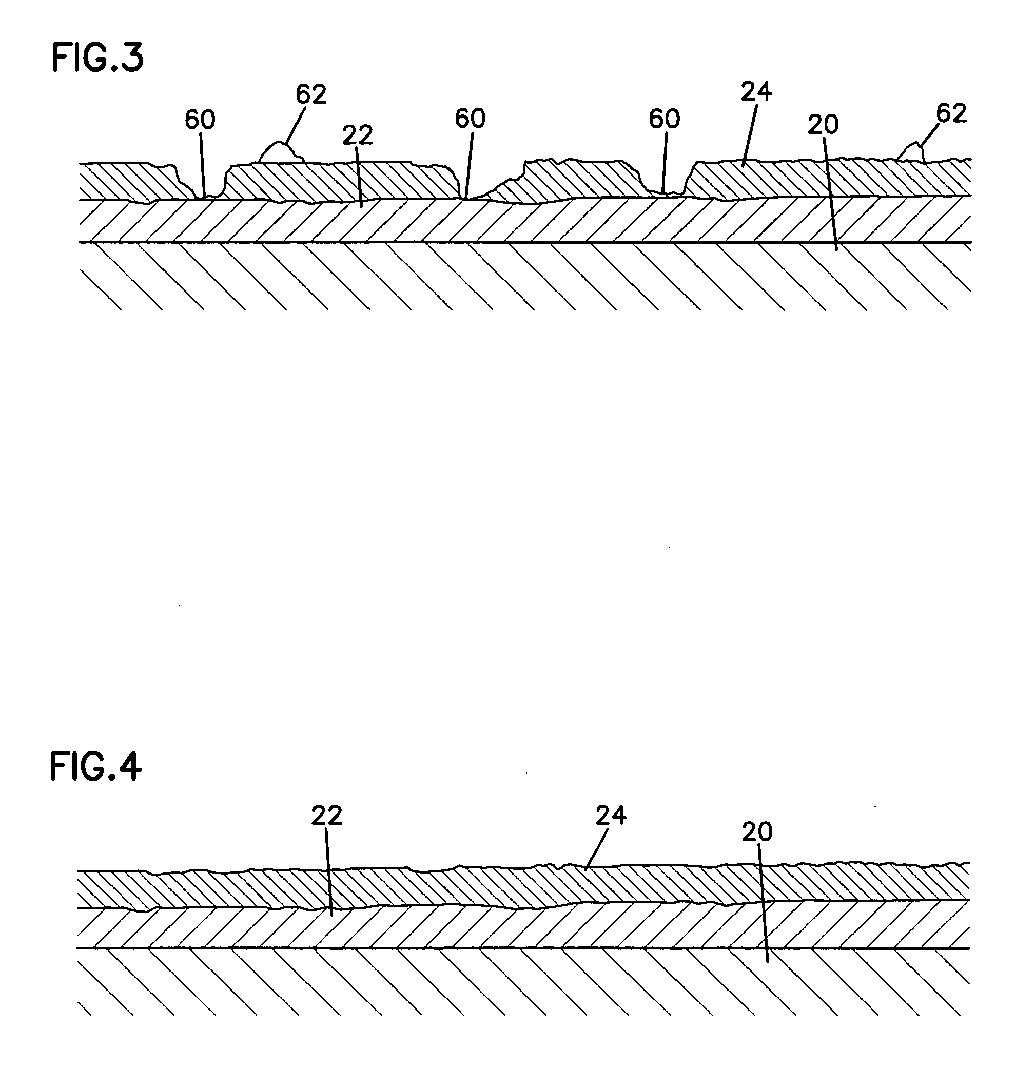
[0030] Referring now to the drawings, and in particular FIG. 1, there is shown a surface or substrate 20 having a first protective coating 22 applied thereto. The coating 22 may be a coating of paint, sealant or other protective layer. The composition of the coating 22 preferably includes an optically activated additive (OAA) such as a luminescent additive acting as a visual indicator in selected types of light such as ultraviolet.

[0031] According to one aspect of the invention shown in FIG. 10, inspection occurs with a projector 40, a camera 42, preferably a digital camera, and a light meter 44, measuring light emitted from the projector 40. The camera 42 and light meter are preferably positioned a predetermined distance D from the first coating 22 so that its thickness may be determined with great precision.

[0032] Prior to coating, for example, a ship's ballast tank, a proprietary paint suitable for the application, typically a marine grade epoxy based paint for such a use, has ...


PUM

PropertyMeasurementUnit
Percent by massaaaaaaaaaa
Coloraaaaaaaaaa
Concentrationaaaaaaaaaa

Abstract

A coating system and method of applying coatings includes applying a first coating having an ultraviolet (UV) indicator therein to an area. The area visually inspected with a UV light and defects are remedied until the area passes the visual inspection. A second coating without a UV indicator is applied over the first coating and visually inspected, with the first coating being visible with a UV light at portions wherein the second coating does not cover the first coating. The second coating is reapplied to portions of the area not passing inspection until the second coating passes inspection. The system also includes three, four or more coating layers in some embodiments with layers having a UV alternated with layers without a UV indicator. The indicator is an inert substance that remains stable to allow for periodic visual inspection over the life of the coating. Visual inspections may be combined with inspections by light metering equipment and a record created for comparison and continued monitoring of the coating system.

Description

[0001] This application is a Continuation-in-Part of application Ser. No. 11 / 223,458, filed Sep. 9, 2005, which is a Continuation-in-Part of application Ser. No. 09 / 958,189, filed Jan. 12, 2002 which is the National Stage of Application PCT / GB01 / 01151, filed Mar. 16, 2001, and which application(s) are incorporated herein by reference.BACKGROUND OF THE INVENTION [0002] 1. Field of the Invention [0003] The present invention relates to a coating system and a method of coating a surface as well as a method for inspecting the quality of the coating at the time of application and continued inspections throughout the life of the coating. [0004] 2. Description of the Prior Art [0005] Coatings and particularly protective coatings on surfaces, whether for marine, industrial or domestic uses depend on effective initial application for superior performance. Among factors affecting this application are surface preparation, coating thickness, continuity and number of coats applied. Moreover, subs...

Claims


Application Information

Patent Timeline
IPC IPC(8): B05B5/00B05D7/00C23C16/52B44F1/10B05D3/00B05D5/06C09D5/22C09D7/12C09D163/00C09D201/00G01B11/06G01N21/64G01N21/88
CPCC09D5/22G01B11/0658G01N21/64G01N21/6456G01N21/8422G01N2021/646G01N2021/8427
Inventor COOPER, WILLIAM ROBERTJESS, HOWARD MITCHELL
Owner LUMINOUS TECH
Why Eureka
Try Eureka