
Self-adhering friction reducing liner and method of use

a friction reducing liner and self-adhering technology, applied in the field of self-adhering friction reducing liner and method of use, can solve the problems of single cycle damage, tissue damage, tearing of biological tissues such as blood capillaries and interface (skin-subcutaneous) layers, and achieve the effect of reducing the magnitude of tangential traction and low friction

Inactive Publication Date: 2007-02-22
TAMARACK HABILITATION TECH
View PDF19 Cites 36 Cited by
  • Summary
  • Abstract
  • Description
  • Claims
  • Application Information

AI Technical Summary

Benefits of technology

The PTFE layer significantly reduces friction in both dry and wet conditions, minimizing tissue trauma and shear-induced damage, allowing for greater comfort and support without causing skin irritation, and can be custom-cut or pre-formed for specific applications.

Problems solved by technology

High shear stresses may cause damage in a single cycle.
Low shear stresses may cause tissue damage when the number of cycles is great.
Shear strain is by its very nature very distortional and, when it exceeds certain levels, results in the tearing of biological tissues such as blood capillaries and interface (skin-subcutaneous) layers.
However, how and when excessive shear stresses / strains occur and how they damage tissue are hard to visualize.
Shear stresses and how they vary over a given area (and vary with time) are very hard to measure; much harder than it is to measure normal pressure.
In addition to the visualization and measurement difficulties just mentioned, there is the fact that few people have better than a vague qualitative awareness of how something called the “coefficient of friction” (C.F.) relates to blisters, abrasions, and calluses.
Examination and knowledge of products on the market indicate that the opportunities for reducing callusing, blistering and abrasions by friction management has been almost entirely unappreciated by designers of shoes, orthoses, prostheses, and many other objects that come in repeated or prolonged contact with the human body.
Foam products are used to line prosthetic sockets, orthoses, and shoe insoles and represent a particularly poor material from the standpoint of friction management.
Damp skin and sock material literally sticks to such foams.

Method used


Image

  • Self-adhering friction reducing liner and method of use
  • Self-adhering friction reducing liner and method of use
  • Self-adhering friction reducing liner and method of use

Examples


Embodiment Construction

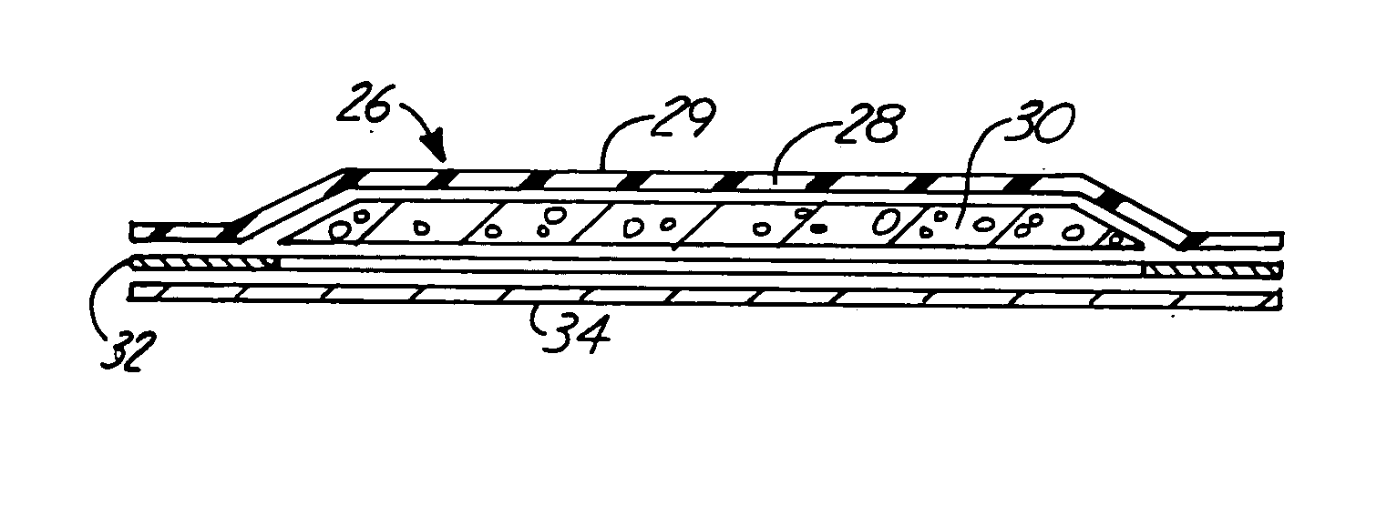
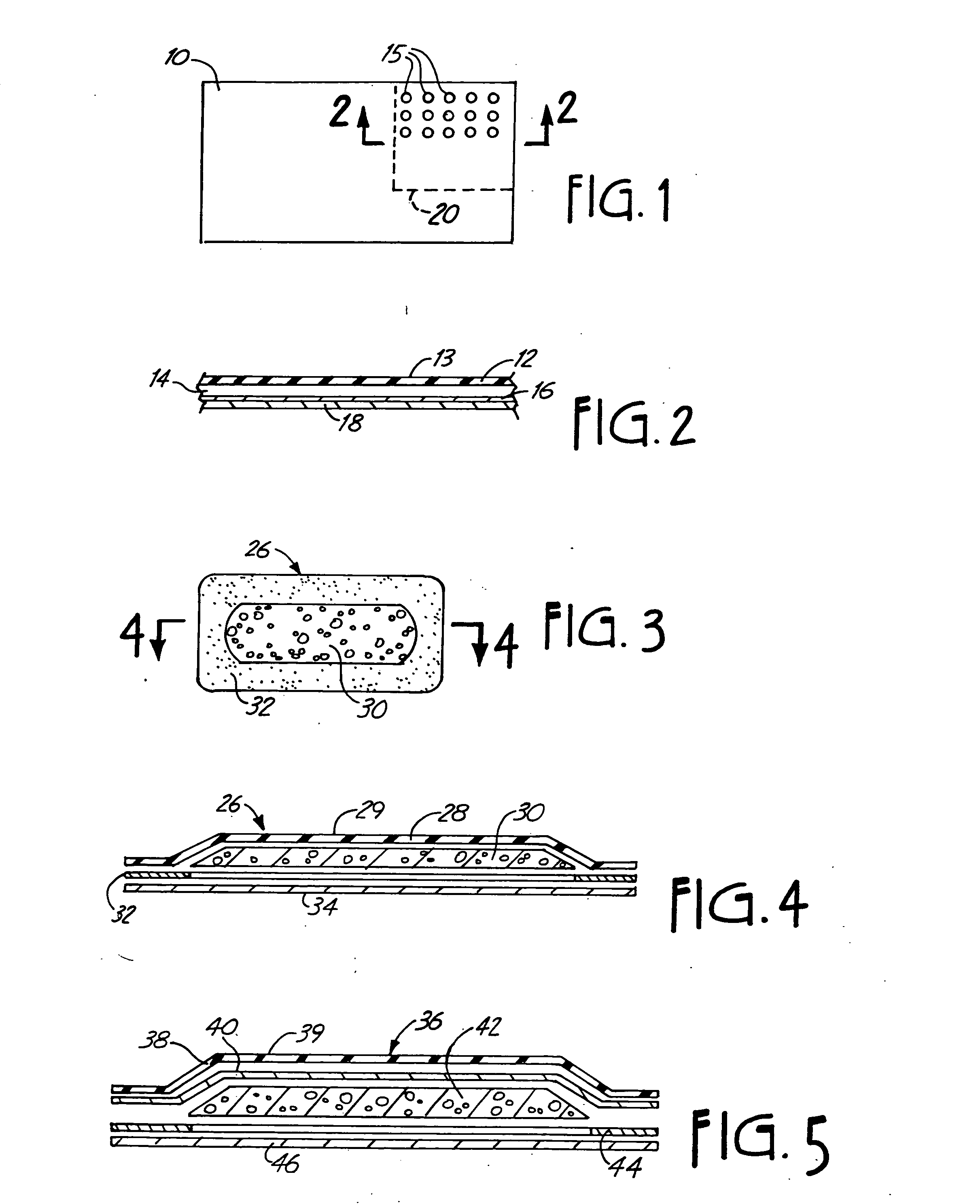
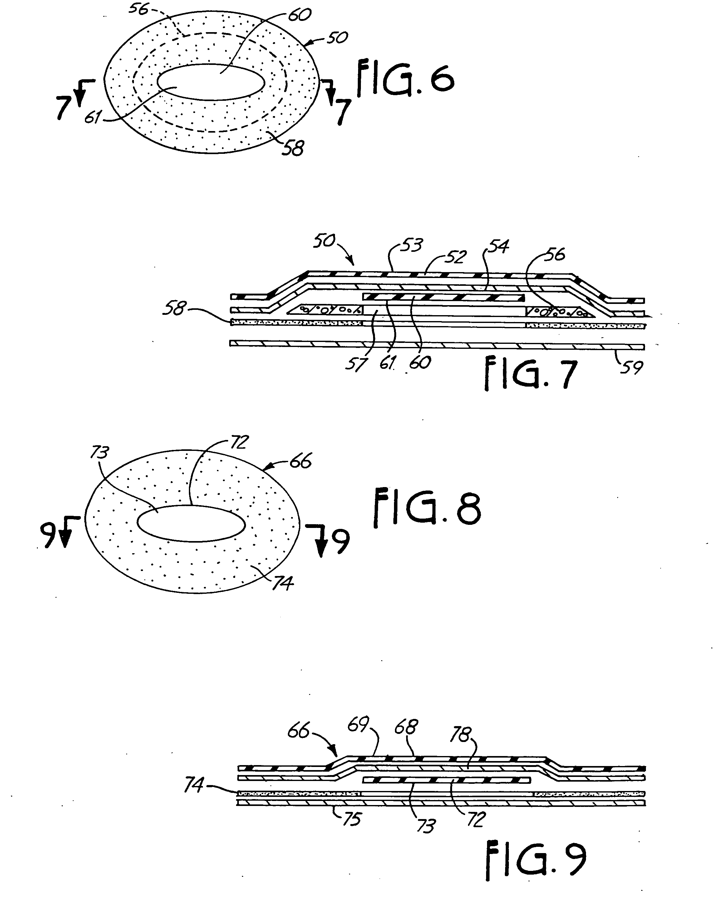
[0040]FIGS. 1 and 2 illustrate a simple form of the invention which includes a composite sheet 10 made in a suitable size, which can be used for cutting individual interface patches or pieces from the sheet. The composite sheet 10 includes a thin film or layer 12 of polytetrafluoroethylene (PTFE). Layer 12 is preferably bonded to a stretch fabric layer 14, such as Lycra or stretch nylon, which also is relatively thin. The top layer of PTFE can be in the range of 2.5 mils thick, and the layer of fabric 14 could be slightly thicker than that, as needed to make a suitable stretch weave. The PTFE film 12 is conformable and will stretch, so that the stretch fabric will cause the PTFE layer to move with it, if it is stretched in any direction. A thin layer of adhesive 16 is shown in the drawings on an opposite side or surface of fabric layer 14 from the PTFE layer 12. A suitable release paper 18 is provided over the adhesive on the fabric.

[0041] The sheet 10 can be used for cutting out v...


PUM

PropertyMeasurementUnit
thickaaaaaaaaaa
widthsaaaaaaaaaa
widthsaaaaaaaaaa

Abstract

A patch of low friction materials, such as a film of polytetrafluoroethylene is sized to provide an area of low friction support for a portion of a human body relative to an object such as a shoe or prosthetic socket. The patch can be lined with foam, or preferably, a stretch fabric so that it will fit around irregular contours of the shoe, or socket, or the skin itself. The patches reduce shear trauma in critical load areas. After identifying regions of high loads, the method comprises applying the patches as needed to avoid sores, calluses, blisters and abrasions.

Description

BACKGROUND OF THE INVENTION [0001] The present invention relates to the use of very low friction material formed into patches or pieces and adhered to the skin or to a surface in contact with the skin (or immediately adjacent material such as a sock) to lower the magnitude of tangential traction of the surface in contact with the skin. The material reduces the likelihood of abrasion, trauma and ulceration in localized areas. [0002] In the prior art, there have been efforts to reduce the co-efficient of friction of materials in load bearing contact with the skin, such as the surface of a lining of a shoe, which slides against a stocking. Also the regions where a limb prosthesis is in load bearing contact with a residual limb have been extensively considered for ways of reducing problems. The co-efficient of friction of smooth leather varies, depending on the moisture content, and when it gets wet can be quite high in friction. Moleskin patches have been sold and used for covering cor...

Claims


Application Information

Patent Timeline
Patent Type & Authority Applications(United States)
IPC IPC(8): A61F15/00A61F13/00A43B17/02A43B17/14A61F2/00A61F2/60A61F2/66A61F2/78A61F2/80A61F5/01
CPCA43B7/1465A43B17/023A43B17/14A43B23/07A43B23/28A61F2/60A61F2/7812A61F2/80A61F5/01A61F15/008A61F2002/30024A61F2002/607A61F2002/6614A61F2002/7806A61F2210/0057A61F2250/0021Y10T442/647A43B7/1464A61F13/02
Inventor CARLSON, J. MARTINSTOLL, STACEY R.
Owner TAMARACK HABILITATION TECH
Learn More