Bone and cartilage implant delivery device

a delivery device technology, applied in the field of bone and cartilage implant delivery devices, can solve the problems of deficient determining the exact depth of a defect, deformation of variable depth, and difficulty in presenting defects, so as to facilitate insertion and pass through soft tissue. , the effect of easy insertion

Inactive Publication Date: 2007-02-22
OSTEOBIOLOGICS
View PDF67 Cites 178 Cited by
  • Summary
  • Abstract
  • Description
  • Claims
  • Application Information

AI Technical Summary

Benefits of technology

[0028] When the implant is delivered to the bone or cartilage defect, the delivery device will often pass through soft tissue. In order to pass through soft tissue more easily and without disrupting the implant, a removable outer sleeve having a bulleted tip is disposed over the outer shaft of a delivery device. Once the delivery device is introduced to the defect, the sleeve may be removed and retracted. Preferably, the removable outer sleeve is clear to allow visualization of the delivery device and the defect. Alternatively, the delivery device has threading on the outside of the outer shaft allowing the device to be twisted into the soft tissue to make insertion easier.
[0029] In a further embodiment of this invention, the implant is delivered to a defect with bioactive fluids, such as blood, blood concentrate or cell suspension. After the implant has been sized and cut to fit the defect, a cap will be placed around the distal end of the outer shaft and bioactive fluids added via a window or slot. Additionally, a centrifuge can be used to load fluids and the delivery device can be made suitable for use in a centrifuge, i.e., structurally able to withstand the forces during centrifugation without leaking or damaging the implant, when loading fluids to the implant.

Problems solved by technology

In implant procedures, defects of variable depths are often presented.
Generally, it is difficult to determine the exact depth of a defect and, therefore, to insert an implant with the correct length.
Current devices for inserting implants, either bone or cartilage transplants or synthetic materials, are deficient in determining defect depth.
However, the tool does not provide means for determining the depth of the defect or for tailoring the length of the implant to fit the defect.
Although this is an improvement in that it allows the length of the bone plug to be determined after harvesting, it also does not provide means to determine the depth of the defect.
However, in certain articulating spaces, such as the ankle, the surfaces are comprised of more complicated geometries.
These articulating surfaces often converge in sharp transition points, creating a complicated geometry for surgical treatment in the event of acute or traumatic injury.
Current therapies are usually limited to debridement, restricted motion, palliative drug therapy, osteochondral transplantation, or as a last resort, joint fusion.
Currently, one common (although unpopular) option is to perform an osteochondral transplant from an articulating surface in the knee to the ankle.
It is often difficult if not impossible to match the geometry between the donor and recipient surfaces, often resulting in marginal or unsatisfactory treatment.
However, current devices for inserting tissue implants, such as bone or cartilage transplants, multi-phase materials, or other synthetic materials, are deficient for inserting implants in complex surfaces which are not planar or smoothly curved.

Method used


Image

  • Bone and cartilage implant delivery device
  • Bone and cartilage implant delivery device
  • Bone and cartilage implant delivery device

Examples


Embodiment Construction

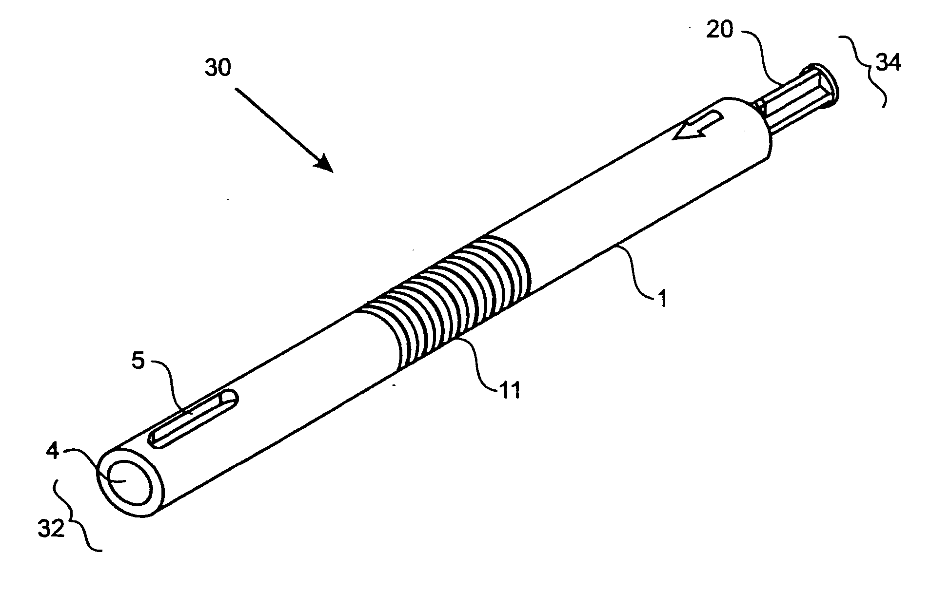
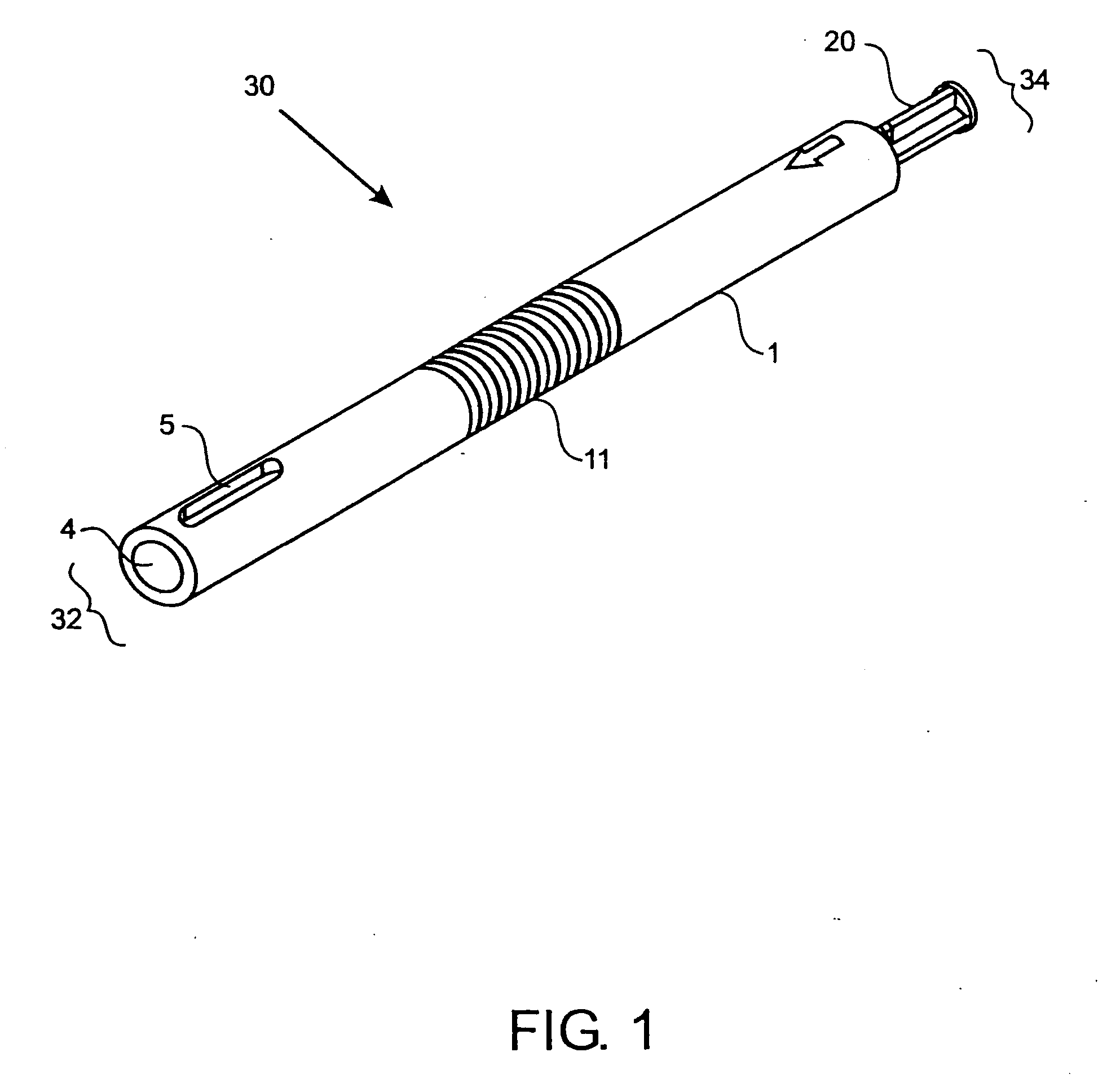
[0062]FIG. 1 shows one embodiment of the implant delivery device 30 of the present invention having a proximal end 34 and a distal end 32. In a preferred embodiment, the delivery device 30 has a length suitable for arthroscopic use, i.e., approximately 4 to 10 inches long, preferably 5-8 inches, with a diameter of about 0.25-1 inch, preferably 0.4-0.75 inches. The implant delivery device 30 includes a hollow tubular outer shaft 1 (also shown in FIG. 3) having an internal bore 4 along the longitudinal axis. The internal bore 4 extends the entire length of the outer shaft 1 from the distal end 32 to the proximal end 34. FIGS. 9A-9C and FIGS. 11A-11C also illustrate the internal bore 4. The distal end 32 of the outer shaft 1 can have one or more slots 5 through the outer shaft 1 for visualizing the implant (not shown in FIG. 1) when the implant is in the delivery device 30. Slots 5 can be any shape that allows the implant to be visualized while disposed in the delivery device 30 and ca...


PUM


Abstract

A method and device for inserting an implant of synthetic material or healthy bone or cartilage into a bone or cartilage defect of unknown depth. The device includes an inner shaft within a hollow outer shaft. One end of the inner shaft of the device is suitable for inserting into the bone or cartilage defect in order to determine the depth, while the other end of the outer shaft is suitable for holding an implant. The implant is cut to fit the defect. The device is partially transparent or translucent to allow visualizing of the implant and defect. The delivery device can be bent or curved to allow the device to be introduced to a defect at different angles and positions. The methods and devices are suitable for delivery of implants to defects having complex shapes.

Description

CROSS-REFERENCE TO RELATED APPLICATIONS [0001] This application is a continuation-in-part of pending U.S. application Ser. No. 10 / 785,388 filed Feb. 23, 2004, which in turn claims the benefit under 35 U.S.C. 119(e) of U.S. Provisional Application No. 60 / 448,965 filed Feb. 21, 2003; this application is also a continuation-in-part of pending a U.S. Application (attorney docket number 90-04 US) filed on Nov. 30, 2005, which in turn claims the benefit under 35 U.S.C. 119(e) of U.S. Provisional Application No. 60 / 632,050 filed Nov. 30, 2004, all of which are incorporated herein in their entirety to the extent not inconsistent herewith.BACKGROUND OF THE INVENTION [0002] This invention relates to an apparatus and methods for performing repairs of cartilage and bone defects. [0003] It is well known in the art that implants can be inserted into damaged bone or cartilage layers to treat injuries to those tissue layers. One type of implant procedure involves inserting plugs of healthy bone or ...

Claims


Application Information

Patent Timeline
Patent Type & Authority Applications(United States)
IPC IPC(8): A61F2/00
CPCA61B17/1635A61B17/1735A61F2/30756A61F2/4601A61F2/4618A61F2/4644A61F2/4657A61F2002/2839A61F2002/3009A61F2002/30217A61F2002/30235A61F2002/30331A61F2002/30471A61F2002/305A61F2002/30538A61F2002/30565A61F2002/30594A61F2002/30601A61F2002/30777A61F2002/3085A61F2002/4635A61F2002/4662A61F2220/0025A61F2220/0033A61F2220/0091A61F2230/0067A61F2230/0069A61F2250/0006A61F2250/0091A61F2002/4627A61B2090/062
Inventor LEATHERBURY, NEIL C.NIEDERAUER, MARK Q.DINGER, FRED B. IIIBLANDFORD, JOSEPH D.
Owner OSTEOBIOLOGICS
Why Eureka
Try Eureka