Coil, coil module and method of manufacturing the same, current sensor and method of manufacturing the same

Inactive Publication Date: 2007-03-01
TDK CORPARATION
View PDF1 Cites 74 Cited by
  • Summary
  • Abstract
  • Description
  • Claims
  • Application Information

AI Technical Summary

Benefits of technology

[0016] According to the coil, coil module or the current sensor, the lead section includes the straight leader extending continuously from the straight-line portion of the innermost turn on the extension thereof, and the semicircle portions are wound so as to climb over the straight leader while they are located in the same layer as the innermost turn in an area other than the straight leader. Therefore, the intensity and the direction of the current magnetic fields which are generated in the straight-line portion of the innermost turn are comparatively stabilized. For this reason, distribution of t

Problems solved by technology

However, in the case of measuring a weak current which is less than 10 A for example, it often happens that only the current magnetic fields generated from one conductor is not adequate even with a current sensor using GMR eleme

Method used


Image

  • Coil, coil module and method of manufacturing the same, current sensor and method of manufacturing the same
  • Coil, coil module and method of manufacturing the same, current sensor and method of manufacturing the same
  • Coil, coil module and method of manufacturing the same, current sensor and method of manufacturing the same

Examples


Embodiment Construction

[0025] An embodiment of the invention will be described in detail hereinafter with reference to the drawings.

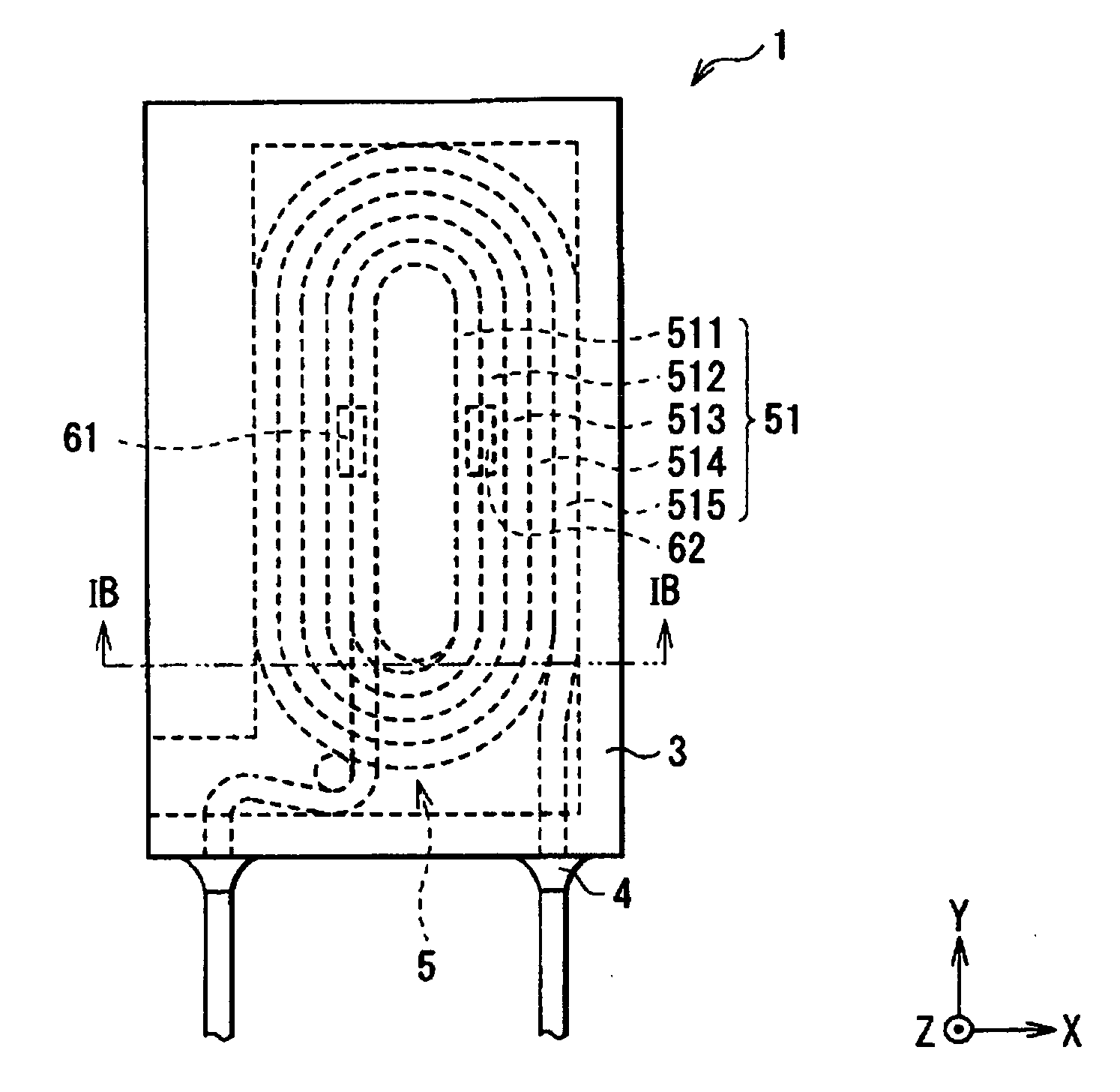
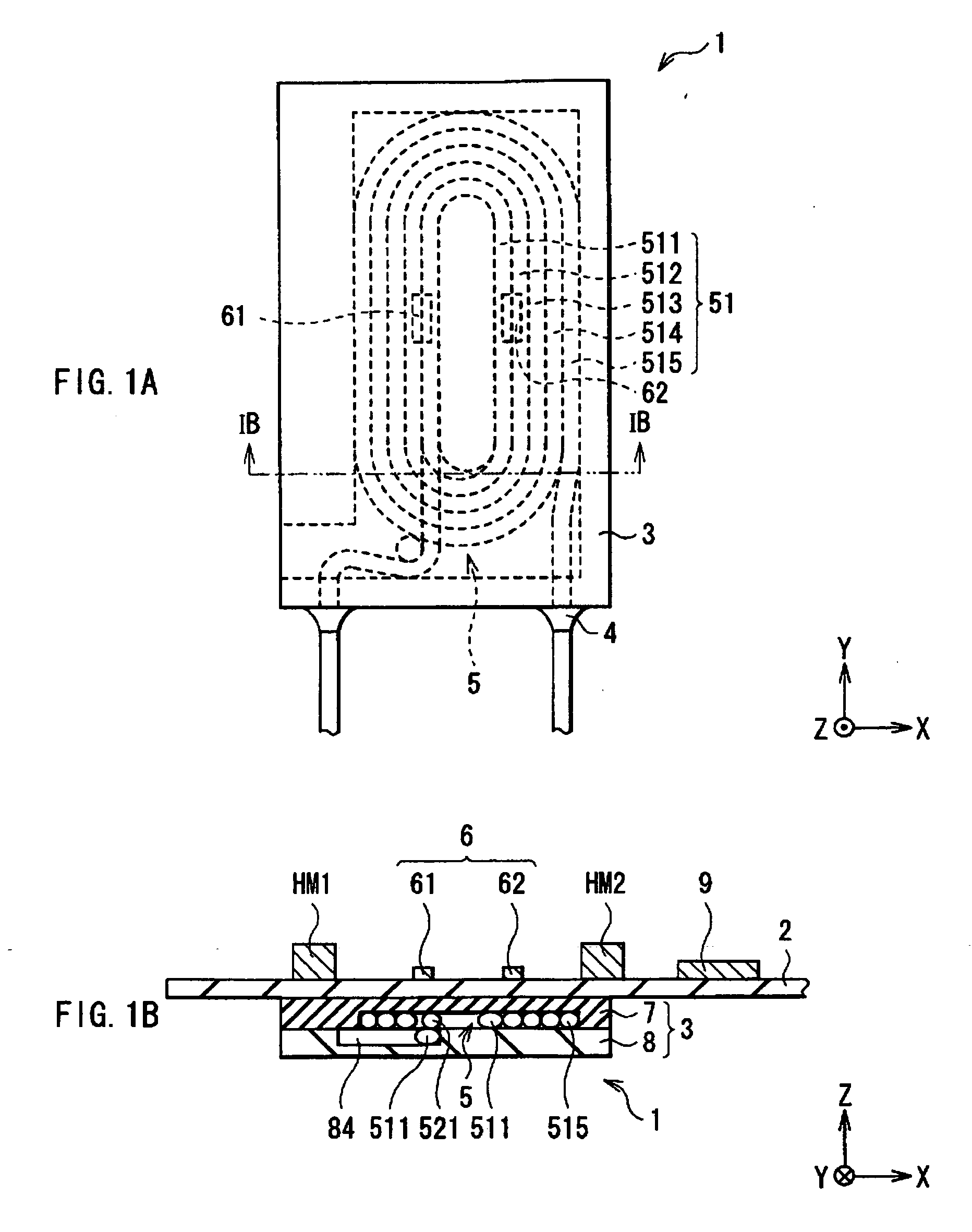
[0026] First, the configuration of a current sensor as one embodiment of the present invention will be described with reference to FIGS. 1A to 6. FIG. 1A and FIG. 1B show a configuration of the current sensor according to the present embodiment provided with a coil module 1 and a magnetic sensor 6. FIG. 1A is a plan view, and FIG. 1B is a cross sectional view taken along line IB-IB of the current sensor illustrated in FIG. 1A seen from the direction indicated by the arrows. However, FIG. 1A shows only the configurations of the coil module 1 and the magnetic sensor 6 for simplification.

[0027] The current sensor has: a housing 3 fixed to a supporting board 2; a coil 5 housed windingly in the inside of the housing 3 so that the both ends of the coil 5 are pulled out from the housing 3 to be fixed respectively by a jointing 4; and a magnetic sensor 6 including GMR elements 61, ...


PUM


Abstract

The current sensor includes: a housing having a base and a lid; and a coil housed in a recess of the base, having winding section consisting of straight-line portions and semicircle portions and lead sections. The lead section includes a straight leader extending continuously from the straight-line portion on the extension thereof, and the semicircle portions are wound so as to climb over the straight leader but are wound in the same layer as the winding section in an area other than that corresponding to the straight leader. For this reason, distribution of the current magnetic fields generated by the coil will become comparatively uniform as a whole. Consequently, current magnetic fields which are sufficiently stabilized current magnetic fields can be applied to a magnetic sensor can be supplied in a uniform direction.

Description

BACKGROUND OF THE INVENTION [0001] 1. Field of the Invention [0002] The present invention relates to a coil which generates current magnetic fields by supplying current, a coil module provided with the coil and method of manufacturing the same, a current sensor provided with the coil and method of manufacturing the same. [0003] 2. Description of the Related Art [0004] In order to accurately detect small control current flowing in a circuit of a control device, a method of connecting resistors in series in the circuit and measuring a voltage drop in the resistors is used in general. In this case, however, a load different from that in a control system is applied, and there is a possibility that an adverse influence may be exerted on the control system. In order to prevent such problem, method of indirectly measuring control current by detecting the gradient of a current magnetic field generated by the control current has used. Specifically, the method is that, for example, a Wheatsto...

Claims


Application Information

Patent Timeline
IPC IPC(8): A01K91/00
CPCG01R15/205G01R15/207
Inventor SHOJI, SHIGERU
Owner TDK CORPARATION
Why Eureka
Try Eureka