Yard hydrant with closure valve check valve

Active Publication Date: 2007-03-01
WCM IND INC
View PDF6 Cites 14 Cited by
  • Summary
  • Abstract
  • Description
  • Claims
  • Application Information

AI Technical Summary

Benefits of technology

[0007] A yard hydrant having a valve body coupled to an inlet water pipe, a standpipe coupled to a valve body, and a head casting coupled to the standpipe. The valve body has a valve seat and a drain port. Disposed within the valve body is a valve or plunger attached to an actuator rod or valve stem that extends vertically through the standpipe and i

Problems solved by technology

The problem with this design is that ground water or other contaminants can enter the y

Method used


Image

  • Yard hydrant with closure valve check valve
  • Yard hydrant with closure valve check valve
  • Yard hydrant with closure valve check valve

Examples


Example

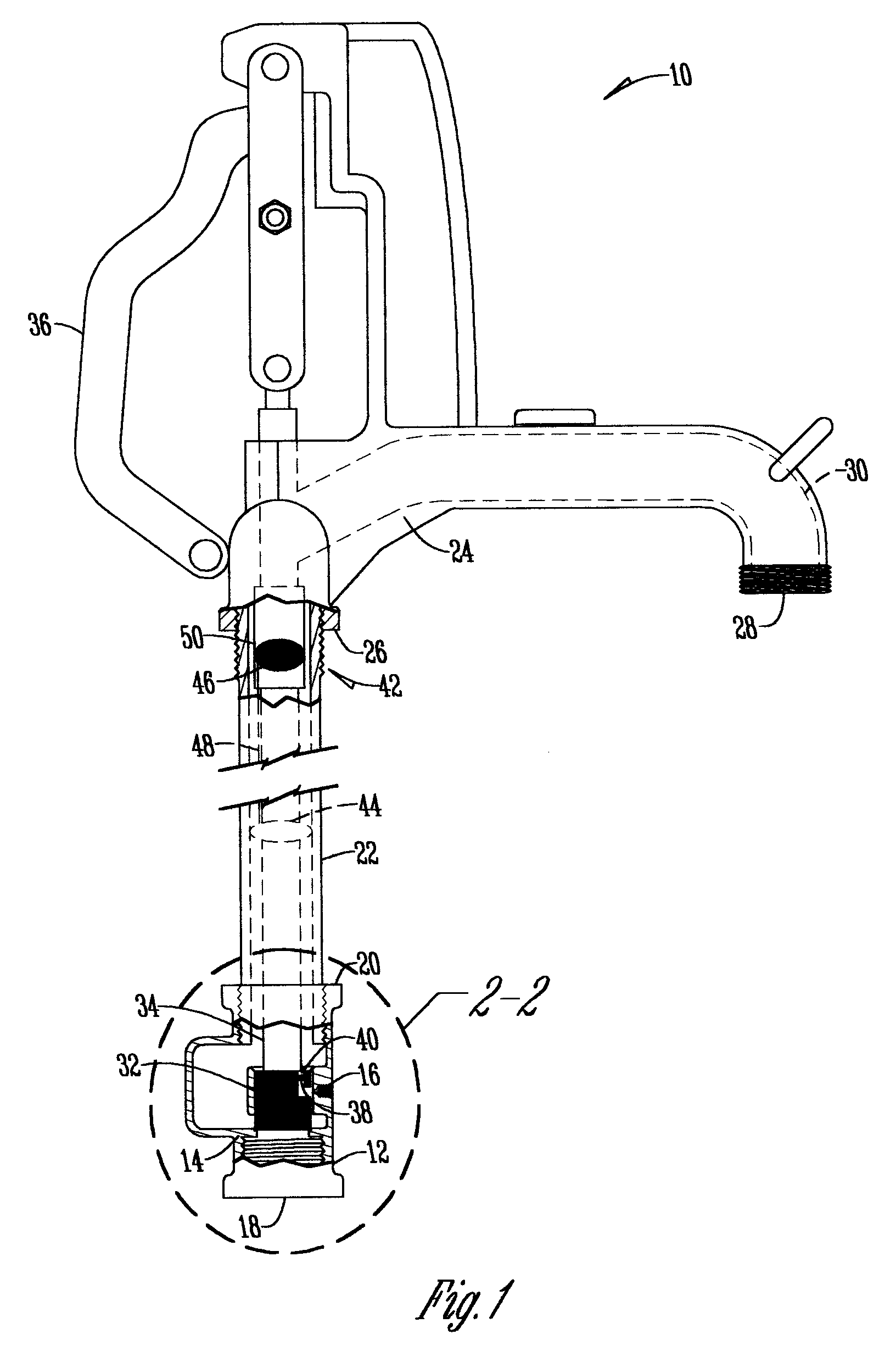
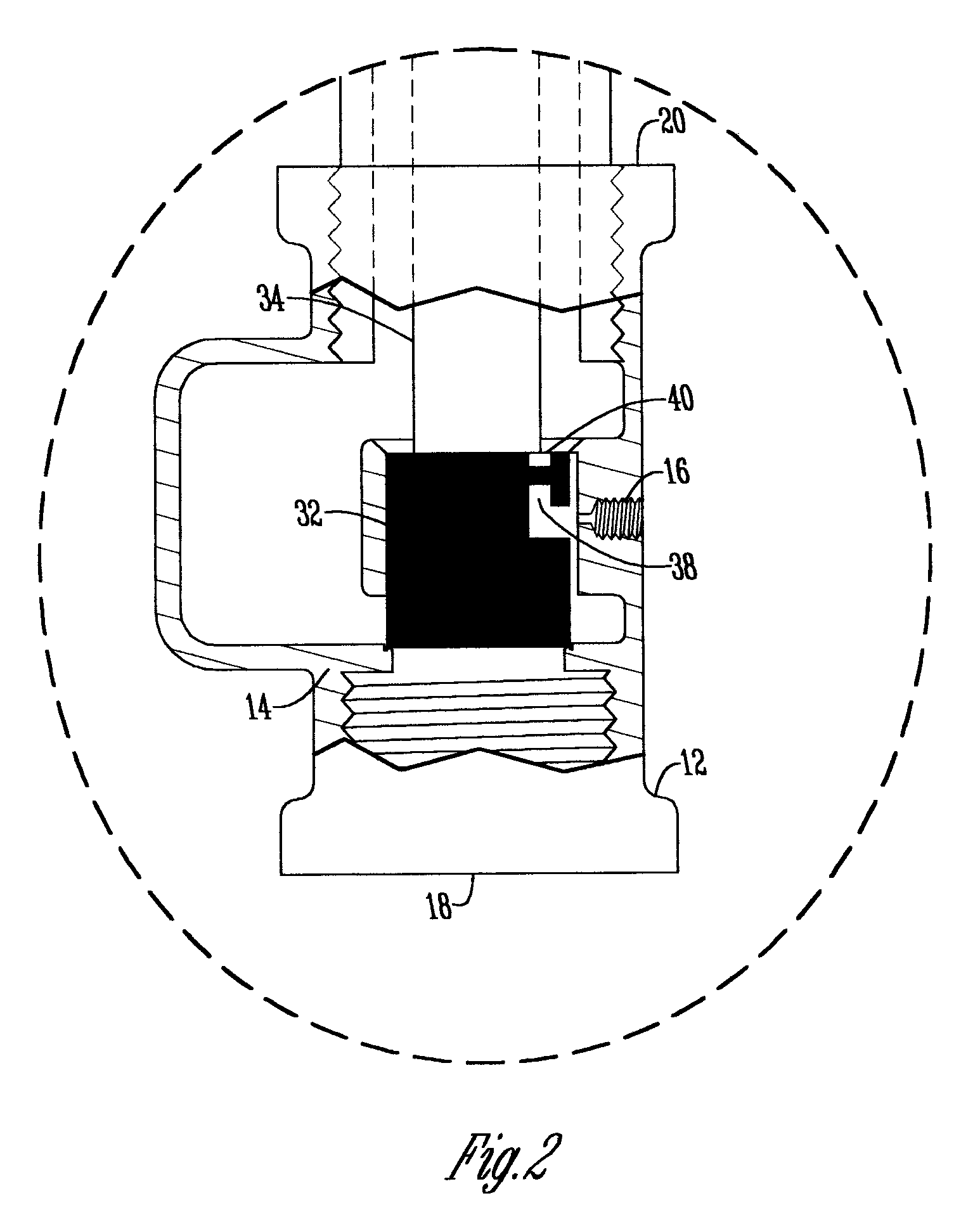
[0010] A yard hydrant 10 has a valve body 12 which has a valve seat 14, a drain port or hole 16, an inlet 18 which is connected to a source of pressurized water (not shown) and an outlet 20 at its top. Connected at one end to the valve body 12 is a standpipe 22 that extends vertically and is connected to a head casting 24 at the opposite end.

[0011] The head casting 24 has an inlet 26 coupled to the standpipe 22 and a discharge conduit or outlet 28 that preferably extends downwardly and outwardly from the head casting 24 and a fluid conduit 30 that extends between the inlet 26 and the outlet 28.

[0012] Disposed within the valve body 12 is a closure valve plunger 32 that is connected to a valve stem or actuator rod 34 that extends from the closure valve 32 through the standpipe 22 and is connected to an actuator device 36 attached to the head casting 24 such as a lever or handle.

[0013] The closure valve 32 has a conduit 38 that is in fluid communication with the drain port 16 at one...


PUM


Abstract

A yard hydrant having a valve body with a valve seat and a drain port. A closure valve disposed within the valve body and engaging the valve seat. The valve body having a conduit in fluid communication with the drain port and a hollow interior of the valve body. A check valve disposed within the conduit to prevent fluid flow from the drain port through the conduit to the hollow interior.

Description

BACKGROUND OF THE INVENTION [0001] This invention is directed toward a yard hydrant, and more specifically to a yard hydrant that prevents contaminants and the like from entering the yard hydrant. [0002] Yard hydrants are well known in the art and have an inlet valve connected to a water supply that is located below the frost line in the ground. When a hydrant is shut off, a drain port at the inlet valve is opened to allow water in the hydrant to drain out. The problem with this design is that ground water or other contaminants can enter the yard hydrant through the same drain port, thus creating an unacceptable cross-connection. [0003] Therefore, there is a need in the art for a yard hydrant that addresses these problems. [0004] A principal objective of the present invention is to provide a yard hydrant that prevents backflow through the drain port. [0005] A further objective of the present invention is to provide a yard hydrant that provides a signal when ground water leaks into t...

Claims


Application Information

Patent Timeline
IPC IPC(8): F16K37/00
CPCE03B9/14E03B9/16F16K27/006Y10T137/7891Y10T137/8342Y10T137/7888Y10T137/5403Y10T137/5497
Inventor BALL, WILLIAM T.
Owner WCM IND INC
Why Eureka
Try Eureka