
Data collection device having dynamic access to multiple wireless networks

a data collection device and wireless network technology, applied in the field of system and method of data communication, can solve the problems of obstructing affecting the free propagation of radio waves, and requiring additional access points

Active Publication Date: 2007-03-01
HAND HELD PRODS
View PDF29 Cites 174 Cited by
  • Summary
  • Abstract
  • Description
  • Claims
  • Application Information

AI Technical Summary

Benefits of technology

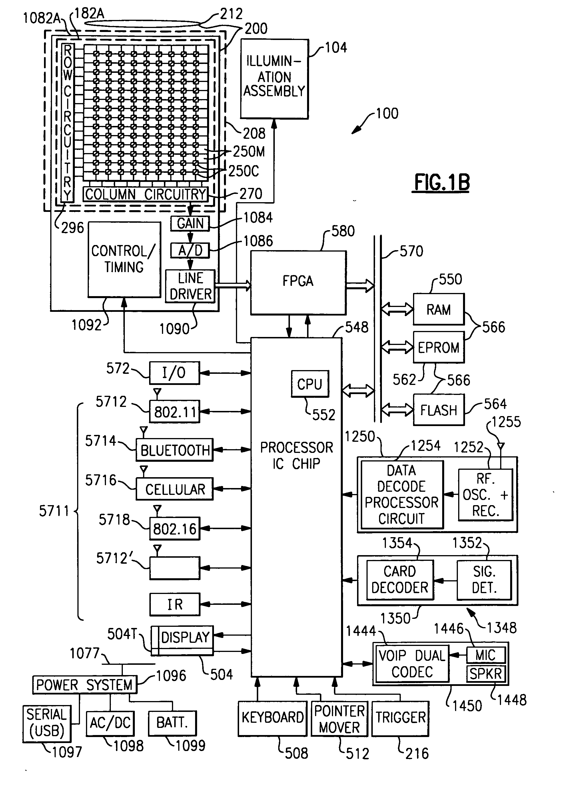
[0025]FIGS. 8a and 8b illustrate an exemplary hand held portable data collection device housing into which all of the components of FIG. 1d may be integrated;

Problems solved by technology

For example, while wireless data collection systems have proliferated, connectivity issues remain with such systems.
In deploying a wireless data collection system a costly “site survey” is often commissioned to search for “dead zones” in work environments Dead zones are prevalent in many data collection work environments, particularly where obstructions to free radio wave propagation exist.
Metal structures and water are known to obstruct the free propagation of radio waves.
The additional access points are costly and typically require connection to an expanded wire-line bus.

Method used


Image

  • Data collection device having dynamic access to multiple wireless networks
  • Data collection device having dynamic access to multiple wireless networks
  • Data collection device having dynamic access to multiple wireless networks

Examples


embodiment 1

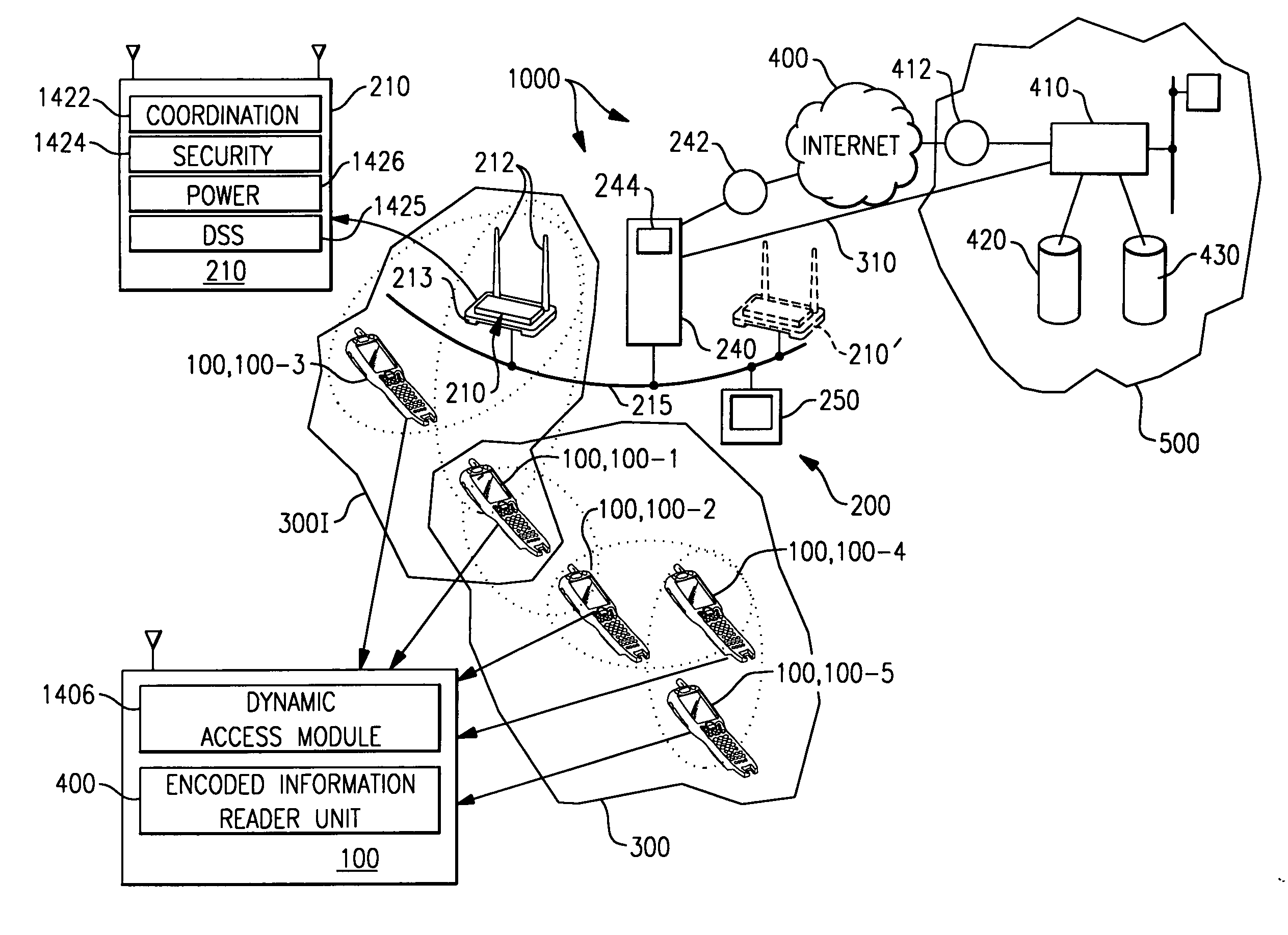
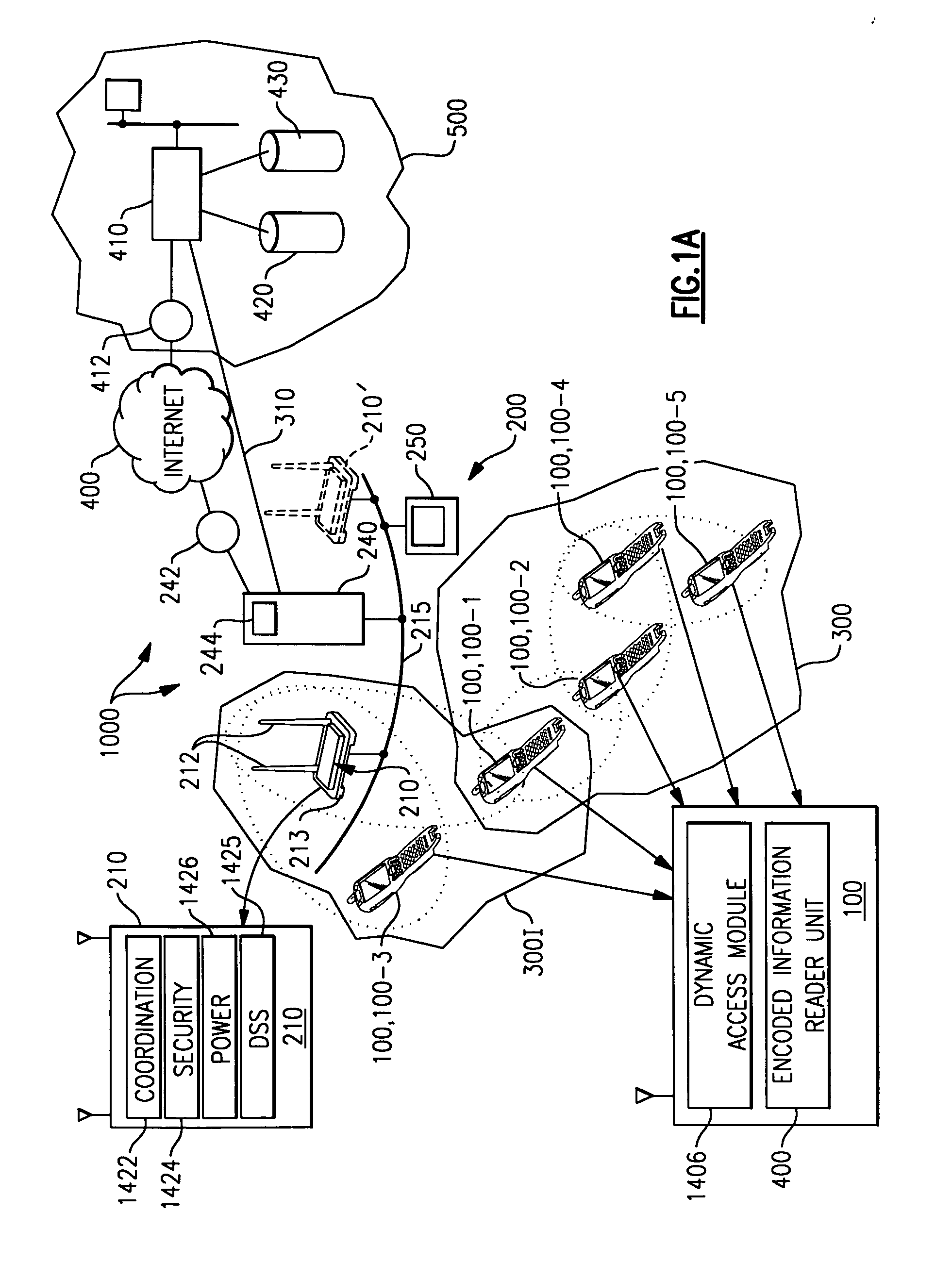
[0098] Referring to embodiment 1, data collection device 100 discriminates whether the data packet being transmitted is streaming video data, still image data, decoded bar code data, decoded RFID data, credit card information data or VOIP data. If device 100 in accordance with packet content discriminator module 1480 determines that the data packet to be transmitted contains streaming video data, latency based routing algorithm module 1467 is activated. If device 100 in accordance with packet content discriminator module 1480 determines that the data packet to be transmitted is still image data (i.e., a frame of image data) data collection device 100 activates power aware routing algorithm module 1468. If device 100 in accordance with packet content discriminator module 1480 determines that the data packet to be transmitted contains decoded bar code data, device 100 activates bit error rate based routing algorithm module 1469. If device 100 in accordance with packet content discrimi...

embodiment 2

[0099] Referring to embodiment 2, data collection device 100 discriminates whether the data packet being transmitted is streaming video data, still image data, decoded bar code data, decoded RFID data, credit card information data or VOIP data. If device 100 in accordance with packet content discriminator module 1480 determines that the data packet to be transmitted contains streaming video data, latency based routing algorithm module 1467 is activated. If device 100 in accordance with packet content discriminator module 1480 determines that the data packet to be transmitted is still image data (i.e., a frame of image data) data collection device 100 activates bit error rate routing algorithm module 1468. If device 100 in accordance with packet content discriminator module 1480 determines that the data packet to be transmitted contains decoded bar code data, device 100 activates power aware based routing algorithm module 1468. If device 100 in accordance with packet content discrimi...


PUM


Abstract

There is described a data collection device that can incorporate an encoded information reading unit that can operate within a system including an access point that is wireline connected to a server. The encoded information reading unit can include at least one of a bar code reading unit, an RFID tag reading unit and a credit / debit card reading unit. Further incorporated in the data collection device can be dynamic access module. The dynamic access communication module enables the data collection device to participate in a self organized network that supports multi-hop data packet transmissions between data collection devices and which further enables the device to transmit data received from a peer device to the system access point.

Description

CROSS REFERENCE [0001] This application claims priority under 35 U.S.C. §119 of Provisional Application No. 60 / 712,037, filed Aug. 26, 2005 entitled “Data Collection Device Having Dynamic Access To Multiple Wireless Networks” as well as priority under 35 U.S.C. §119 of Provisional Patent Application No. 60 / 725,001, filed Oct. 7, 2005 entitled Data Collection Device Having Dynamic Access to Multiple Wireless Networks.” The priority of each of the above applications is claimed and each of the above applications is incorporated herein by reference in its entirety.FIELD OF THE INVENTION [0002] The invention is generally related to system and methods of data communication and is specifically related to a system and method of data communication in a data collection system having data collection devices. BACKGROUND OF THE INVENTION [0003] In recent years significant advances have been made in the art of data collection devices and networks containing the same. [0004] In U.S. Pat. No. 5,900...

Claims


Application Information

Patent Timeline
Patent Type & Authority Applications(United States)
IPC IPC(8): G06K7/10H04W40/12H04W40/28H04W40/30H04W74/00H04W84/18H04W88/04H04W88/06H04W88/08
CPCH04W8/005H04W84/18H04W40/28H04W40/30H04W74/00H04W76/023H04W84/20H04W88/04H04W88/06H04W88/08H04W40/246H04L12/189H04M3/4228H04M7/006H04W8/24H04W52/0206H04W84/12H04W40/12H04W76/14Y02D30/70
Inventor WANG, YNJIUN
Owner HAND HELD PRODS
Learn More