Supercharge Your Innovation With Domain-Expert AI Agents!

Armature and motor on which the armature is mounted

a technology of armatures and motors, applied in the direction of dynamo-electric components, dynamo-electric machines, magnetic circuit shapes/forms/construction, etc., can solve problems such as electric short circuits, and achieve the effect of preventing electric short circuits between laminated cores and conductors

Inactive Publication Date: 2007-03-01
NIDEC CORP
View PDF6 Cites 20 Cited by
  • Summary
  • Abstract
  • Description
  • Claims
  • Application Information

AI Technical Summary

Benefits of technology

[0008] The laminated cores are bent annularly. At this time, the size of the gap in the circumferential direction of the inner peripheral surfaces of the insulators neighboring in the circumferential direction is decreased by bending the laminated cores. Since the size of the gap is set so as to be smaller than the diameter of the conductor, when the laminated cores are bent annularly, the conductor can be prevented from being caught between the core back parts. Consequently, occurrence of electric short circuit between the laminated cores and the conductor can be prevented.

Problems solved by technology

However, when the laminated cores are bent in the annular shape, there is the possibility such that the conductor that runs between the teeth is caught between the neighboring laminated cores and, when current is passed in such a state, electric short-circuit occurs.

Method used


Image

  • Armature and motor on which the armature is mounted
  • Armature and motor on which the armature is mounted
  • Armature and motor on which the armature is mounted

Examples


Embodiment Construction

General Structure of Brushless Motor

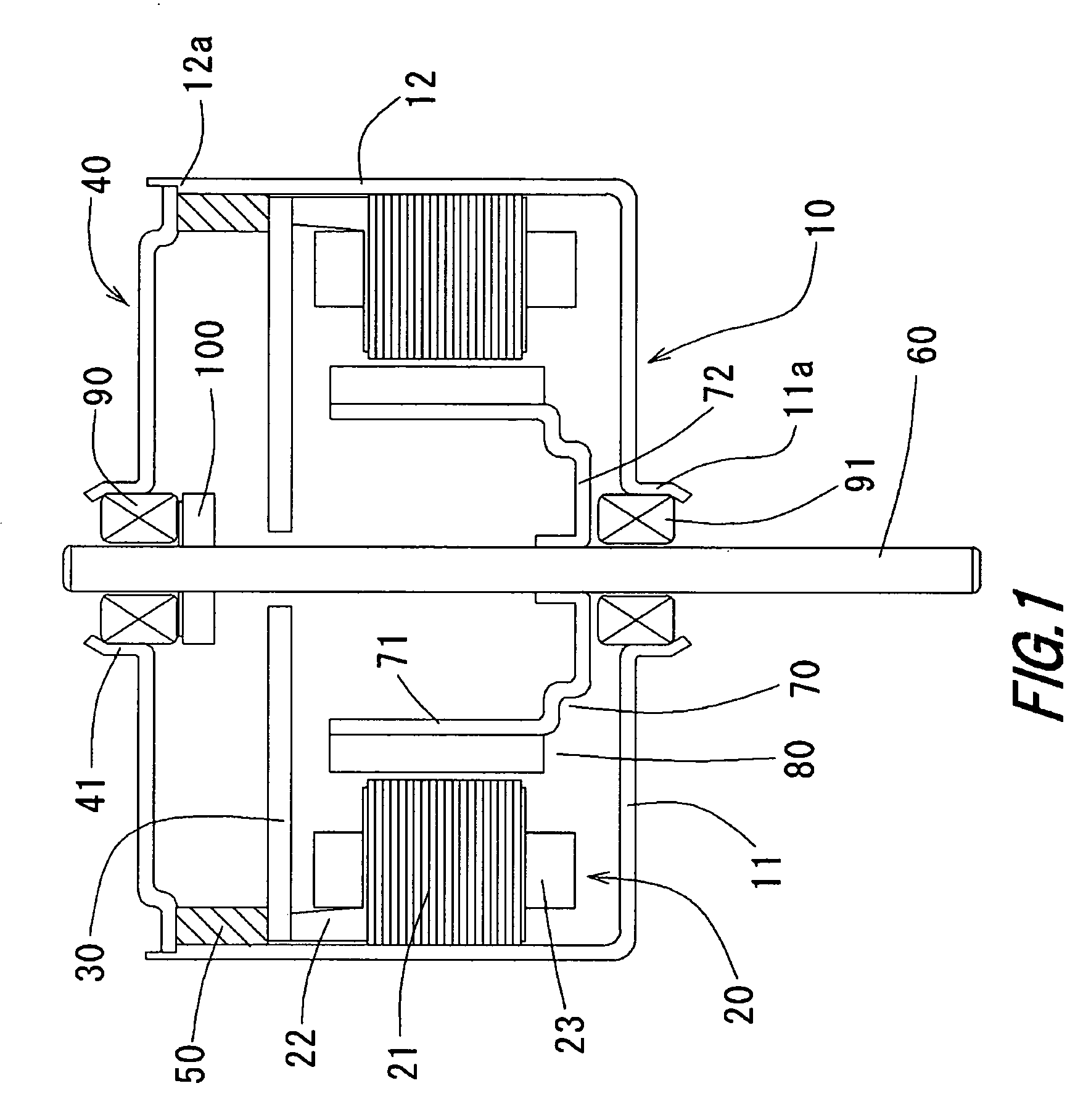
[0015]FIG. 1 is a schematic cross section showing an example of an embodiment of a brushless motor according to the present invention. In the following, description of directions such as upper and lower directions in the specification is description corresponding to the diagrams, and the directions are not limited in actual embodiments.

[0016] Referring to FIG. 1, in a cover 10 formed in a bottomed cylindrical shape with the upper side open, a lower-side annular projection 11a which is opened in a center part of a bottom 11 is formed. In a cylindrical part 12 of the cover 10, an armature 20 formed in an annular shape is fixed.

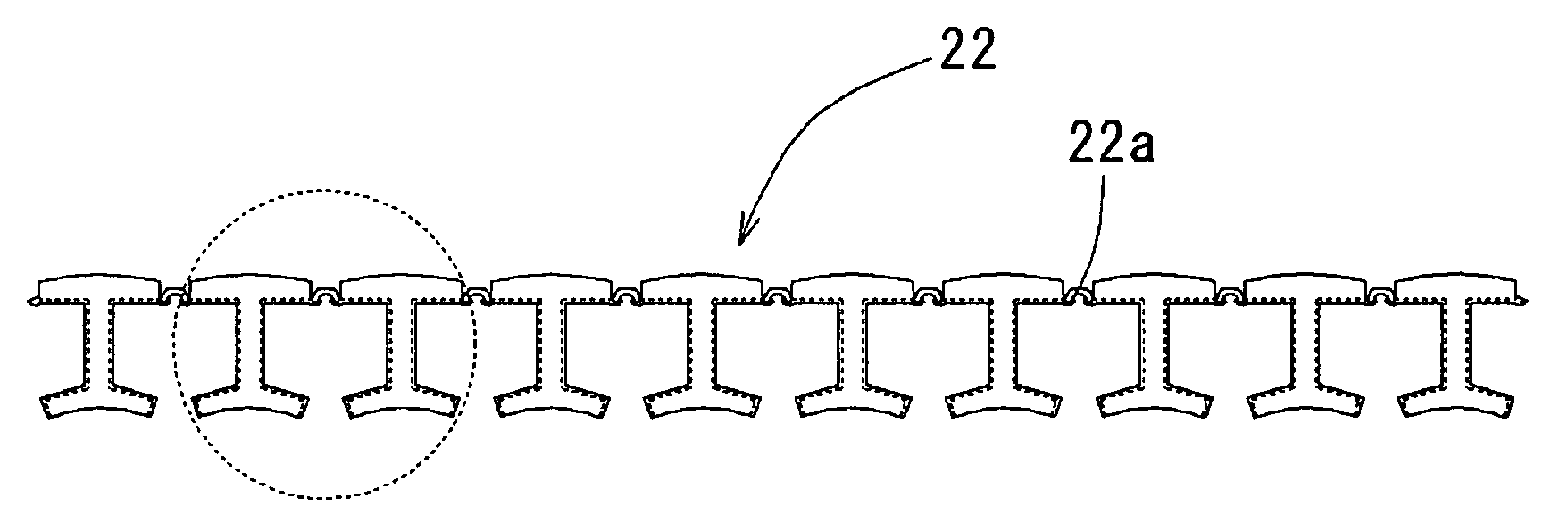
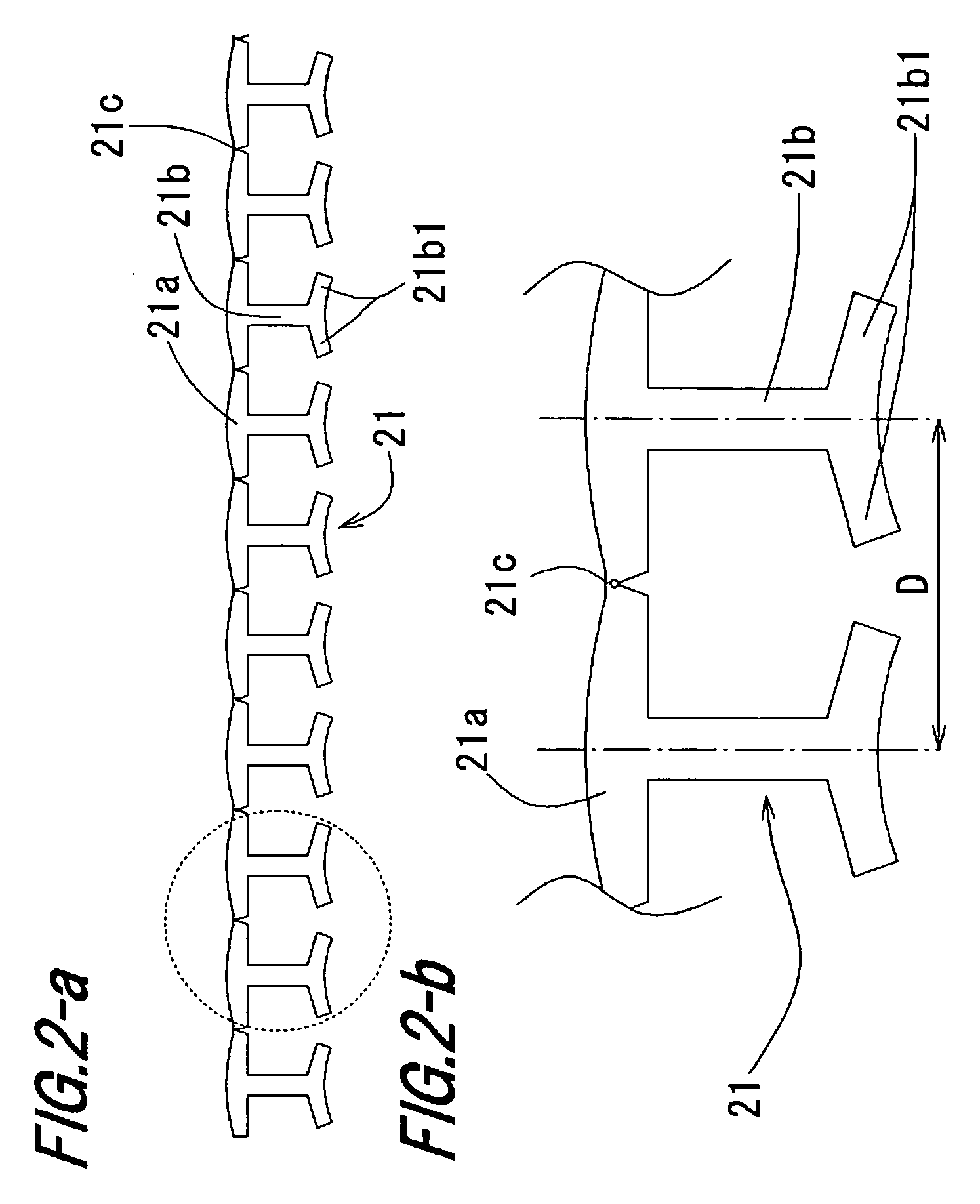
[0017] The armature 20 is constructed by a laminated core 21 in which thin films are laminated, an insulator 22 covering the laminated core 21, and a coil 23 formed by winding a conductor around the laminated core 21 and the insulator 22 in a plurality of layers. A circuit board 30 which rotates when power is supplied from...


PUM


Abstract

An extension part of an insulator covering a part of a coupling portion of a laminated core of an armature is inclined to the inside in the radial direction along the coupling part. A inclined face which is extended inward in the radial direction is formed in the cylindrical part of the armature. By forming the armature in an annular shape, a gap which is almost parallel or narrowed to the inside in the radial direction is formed between neighboring inclined faces. The gap is formed to be smaller than the diameter of a conductor.

Description

BACKGROUND OF THE INVENTION [0001] 1. Technical Field [0002] The present invention relates to an armature mounted on a motor and, more particularly to the shape of an insulator for insulating the armature. [0003] 2. Description of Related Art [0004] One of methods for improving the space factor of a conductor wound around an armature is a method of winding a conductor around laminated cores which are arranged in an almost straight state and, after that, bending the laminated cores in an annular shape. When the laminated cores are in a straight state, the intervals between neighboring teeth can be made large. Therefore, the space factor of the conductor can be improved, and it can contribute to increase in the efficiency of the motor. [0005] The conductor is wound continuously so as to run from a predetermined tooth to another predetermined tooth. However, when the laminated cores are bent in the annular shape, there is the possibility such that the conductor that runs between the te...

Claims


Application Information

Patent Timeline
Patent Type & Authority Applications(United States)
IPC IPC(8): H02K1/28H02K1/12
CPCH02K3/325H02K1/148
Inventor YAMAMOTO, MASATOMORI, YOICHIURAKAMI, HITOSHI
Owner NIDEC CORP
Features
  • R&D
  • Intellectual Property
  • Life Sciences
  • Materials
  • Tech Scout
  • Unparalleled Data Quality
  • Higher Quality Content
  • 60% Fewer Hallucinations
Learn More