Failure detecting device for a load driving system

a technology of failure detection and load driving system, which is applied in the direction of electric variable regulation, process and machine control, instruments, etc., can solve the problems of system application to a case, large quantity of electric current likely to flow, and the failure mode (disconnection) of a load or a load connecting line with no change in load terminal voltage cannot be detected, so as to achieve safe and quick anomaly detection, the effect of preferabl

Inactive Publication Date: 2007-03-01
MITSUBISHI ELECTRIC CORP
View PDF7 Cites 9 Cited by
  • Summary
  • Abstract
  • Description
  • Claims
  • Application Information

AI Technical Summary

Benefits of technology

[0013] Further, enabling anomalies to be detected while the driving means is off makes feed to the load under a condition of the ground failure or the power source short circuit of the load or operation of the driving means under a condition of the on failure of the driving means unnecessary, so that safe and quick anomaly detection can be achieved.
[0014] Especially, in view of prevention and safety, sophistication of the anomaly detection of a connecting state of a load and the failure detection of the driving means at a low cost has been strongly required for a multiphase connecting load driving system represented by a rotary electric machine mounted to rolling stock or an automobile. The invention can provide a preferable anomaly detecting system.

Problems solved by technology

This causes a problem that an open failure mode (disconnection) of a load or a load connecting line with no change in load terminal voltage cannot be detected.
Accordingly, the system cannot be applied to a case that it is judged whether current application causes a problem or not in an initial step for starting current application to a load from a stop state.
This causes a problem that a large quantity of electric current is likely to flow when the load is in a failure condition such as a ground fault and a power-source short circuit.

Method used


Image

  • Failure detecting device for a load driving system
  • Failure detecting device for a load driving system
  • Failure detecting device for a load driving system

Examples


embodiment 1

[0024] Now, Embodiment 1 of the invention will be described hereinafter on the basis of the drawings.

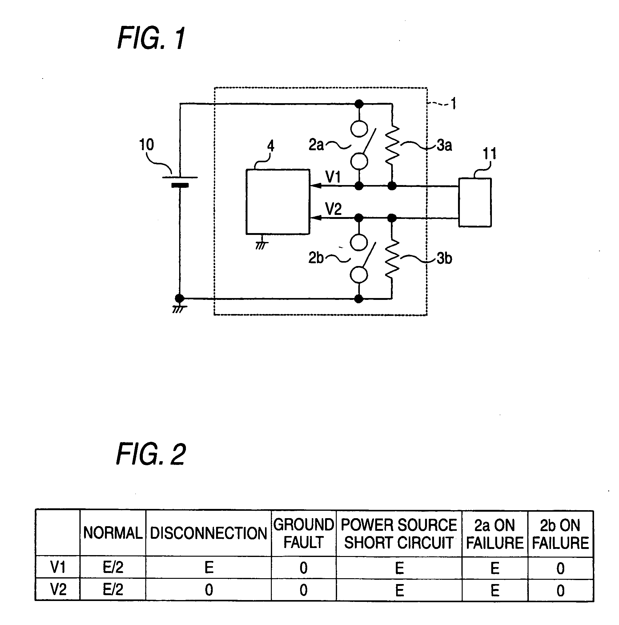
[0025]FIG. 1 is a circuit diagram showing an example of a structure in accordance with Embodiment 1. A load driving system 1 includes an upper arm driving means 2a formed from a semiconductor element such as an FET, for example, and a lower arm driving means 2b also formed from a semiconductor element such as an FET. One end of each driving means is connected to a direct current power source 10 such as a battery while the other end is connected to a load 11 such as an electric motor.

[0026] A resistor element 3a is connected in parallel to the upper arm driving means 2a. A resistor element 3b is connected in parallel to the lower arm driving means 2b. It is arranged that on / off control of the respective driving means 2a and 2b cause feed or a break to the load 11. Further, the other ends of the respective driving means 2a and 2b are connected with a later-mentioned load condition an...

embodiment 2

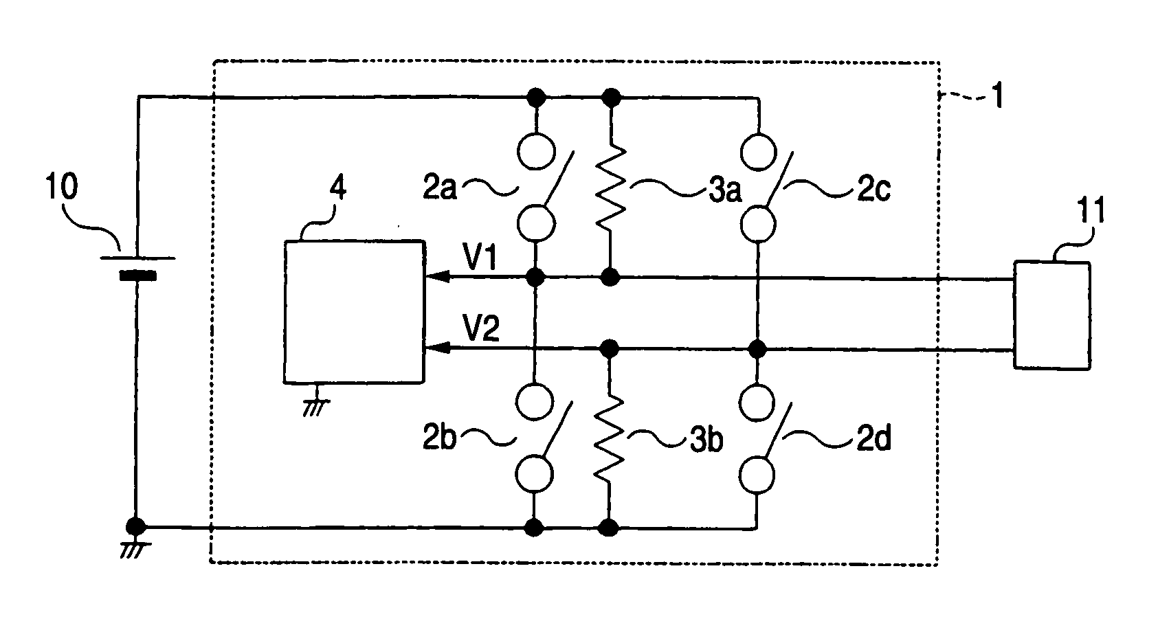
[0039] Now, Embodiment 2 of the invention will be described on the basis of the drawings. FIG. 3 is a circuit diagram showing an example of a structure in accordance with Embodiment 2. In the load driving system 1 in Embodiment 2, a first driving means including the upper arm element 2a, which is formed from a semiconductor element such as an FET, and the lower arm element 2b, which is also formed from a semiconductor element such as an FET and connected in series with the upper arm element 2a, and a second driving means including the upper arm element 2c, which is formed from a semiconductor element such as an FET, and the lower arm element 2d, which is also formed from a semiconductor element such as an FET and connected in series with the upper arm element 2c, are connected to the direct current power source 10 such as a battery while the load 11 and the load condition anomaly detecting means 4 are connected between a connecting point of the upper arm element 2a and the lower arm...

embodiment 3

[0051] Now, Embodiment 3 of the invention will be described on the basis of the drawings. FIG. 5 is a circuit diagram showing an example of a structure in accordance with Embodiment 3. In the load driving system 1 in Embodiment 3, a first driving means including the upper arm element 2a, which is formed from a semiconductor element such as an FET, and the lower arm element 2b, which is also formed from a semiconductor element such as an FET and connected in series with the upper arm element 2a, a second driving means including the upper arm element 2c and the lower arm element 2d connected to the upper arm element 2c in series, the second driving means being formed similarly to the first driving means, and a third driving means including the upper arm element 2e and the lower arm element 2f connected to the upper arm element 2e in series, the third driving means being formed similarly to the first driving means, are respectively connected in parallel to the direct current power sour...


PUM


Abstract

A failure detecting device for a load driving system including an upper arm driving means connected between a positive electrode of a direct current power source and one end of a load and a lower arm driving means connected between a negative electrode of the direct current power source and the other end of the load for on/off-controlling the respective driving means to control a voltage or an electric current to be supplied to the load, the failure detecting device including: resistor elements respectively connected in parallel to the upper arm driving means and the lower arm driving means; and a load condition anomaly detecting means for detecting an anomaly of the load driving system including the load or wiring to the load by observing terminal voltage of one or both of the load terminals.

Description

BACKGROUND OF THE INVENTION [0001] 1. Field of the Invention [0002] The present invention relates to a failure detecting device for detecting anomalies of a load and condition of connection of the load in a load driving system. [0003] 2. Related Art [0004] A conventional load driving system, an electric motor-drive device, for example, including a failure detecting means comprising: high resistors respectively connected in parallel to at least two FETs in which a source of one FET of a bridge circuit formed from four FETs (field effect transistors) as an electric motor driving means is connected to a drain of the other FET to form an arm, the high resistors having sufficiently larger resistance value than the resistance value of the case of an on failure of the FET; and a voltage detection means for detecting a voltage of the electric motor connected between output terminals of the bridge circuit. In the electric motor-drive device, providing the high resistors causes voltage values...

Claims


Application Information

Patent Timeline
Patent Type & Authority Applications(United States)
IPC IPC(8): G05F1/00H02M7/04H02M7/5387
CPCH02H7/1225
Inventor MATSUOKA, SHOUGO
Owner MITSUBISHI ELECTRIC CORP
Why Eureka
Try Eureka