Spot beam antenna boresight calibration using GPS receivers

a technology of gps receiver and beam antenna, which is applied in the field of system and method for calibrating the pointing of antennas, can solve the problems of reducing the beamwidth of such antennas, reducing the effectiveness of countermeasures, and many significant and very costly problems, so as to improve the observability of satellites, improve the accuracy of pointing, and be readily available

Active Publication Date: 2007-03-01
THE BOEING CO
View PDF4 Cites 15 Cited by
  • Summary
  • Abstract
  • Description
  • Claims
  • Application Information

AI Technical Summary

Benefits of technology

[0014] This process can be repeated many times and performed using a plurality of GPS receivers, and multiple measurements can be collected over several orbits. The use of multiple measurements reduces noise effects and maximizes alignment error observability (i.e. provides a wide range of geometries to calibrate over).
[0016] GPS receivers are inexpensive, usually portable, and readily available as compared to a large fixed ground antenna. If mobile GPS receivers are used, this approach also improves satellite observability by allowing calibration over many geographical areas, requires fewer measurements and hence produces faster convergence and a more accurate alignment estimate as compared to using fixed ground antennas.
[0017] By directly solving the technical problem of minimizing alignment errors between satellite attitude sensor(s) and the antenna signal boresight, this invention also solves a host of other problems. It (1) improves mission effectiveness in a GPS jamming environment: increasing kill probability, reducing number of sorties and weapons and minimizing collateral damage, (2) minimizes unintentional RF interference to other systems, (3) enables antenna boresight angular calibration using one or more GPS receivers, (4) eliminates the need to perform on-orbit calibration using a large fixed ground antenna and improves scheduling availability, (5) enables satellite observation from anywhere and anytime on Earth using a mobile GPS receiver.
[0018] Advantageously, the GPS receiver and calibration (power measurement) receiver can be a single integrated item, so that location information at the ground station is inherently known by the system at all times. This avoids the problem of determining the ground station location for each new ground station. The system also uses a combination of proven existing advanced technologies (GPS receivers) and methodologies (Kalman Filters and least squares estimation) to allow fully automatic operation with high accuracy. The system also allows the ground stations used for calibration to be rapidly relocated, and can even be set up aboard ocean-going vessels.

Problems solved by technology

Since such signals have military applications, countermeasures can be expected to be applied to reduce their effectiveness.
However, the high gain of such antennas is obtained at the cost of reduced beamwidth.
Improperly pointing a spot beam antenna can result in many significant and very costly problems.
The pointing problem means that GPS users (e.g., GPS-based weapon systems) in the targeted area of operation may not receive the spot beam GPS signal (rendering the weapon useless), and other equipment in the neighboring region may be unintentionally disrupted by this high-gain signal.
This problem will also result in greater collateral damage and an increased number of sorties and weapons.
While effective, the ground calibration approach renders inaccurate solutions due to launch vehicle vibration and other effects in between the calibration on the ground and the final activation of the satellite in space.
Unfortunately, this technique requires large fixed ground antennas which have limited availability due to resource sharing among different satellite constellations.
They thus may require additional ground stations, more frequent calibration, further burdening the ground resources.
The ground antennas are also dedicated to the purpose of calibration, and are costly.
In addition, due to a limited number of fixed ground antenna locations, the geometry of the satellite and ground system often limits the effectiveness of such on-orbit systems.
Such problems are worse for non-geosynchronous satellites, as they are moving with respect to the Earth's surface.

Method used


Image

  • Spot beam antenna boresight calibration using GPS receivers
  • Spot beam antenna boresight calibration using GPS receivers
  • Spot beam antenna boresight calibration using GPS receivers

Examples


Embodiment Construction

[0024] In the following description, reference is made to the accompanying drawings which form a part hereof, and which is shown, by way of illustration, several embodiments of the present invention. It is understood that other embodiments may be utilized and structural changes may be made without departing from the scope of the present invention.

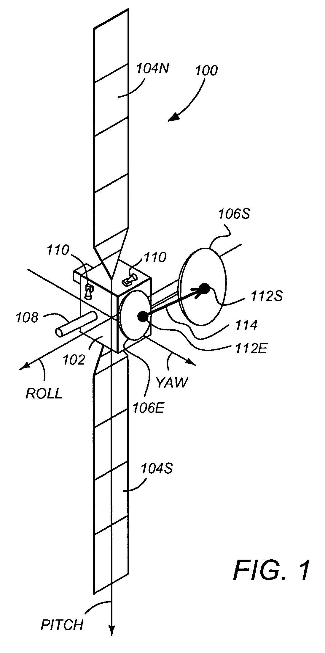
[0025]FIG. 1 illustrates a three-axis stabilized satellite or spacecraft 100. The satellite 100 has a main body 102 (which may be referred to as the “satellite bus”), one or more solar panels 104, one or more navigation beam antennas 106E and 106S, and a telemetry and command antenna 108 which is used to communicate with a control ground station. The satellite 100 may also include one or more sensors 110 to measure the attitude of the satellite 100. These sensors may include sun sensors, earth sensors, and star sensors. Since the solar panels are often referred to by the designations “North” and “South”, the solar panels in FIG. 1 are refe...


PUM


Abstract

A method and apparatus for calibrating such a spot beam antenna by use of scanned spot beam signal characteristics measured by a plurality of ground based navigation receivers is disclosed.

Description

BACKGROUND OF THE INVENTION [0001] 1. Field of the Invention [0002] The present invention relates to systems and methods for calibrating the pointing of antennas used in satellite-based navigation, and in particular, to a method and apparatus for calibrating such antennas by use of scanned spot beam signal characteristics measured by a plurality of navigation receivers. [0003] 2. Description of the Related Art [0004] The Global Positioning System (GPS) is a satellite system that transmits navigation signals that are received by navigation receivers and used to determine the position of the receiver to a high degree of accuracy. Currently, GPS provides standard service to commercial receivers, and a higher accuracy signal to military receivers designed to receive them. [0005] Since such signals have military applications, countermeasures can be expected to be applied to reduce their effectiveness. One such countermeasure is jamming. To increase the effectiveness of the GPS signals in...

Claims


Application Information

Patent Timeline
Patent Type & Authority Applications(United States)
IPC IPC(8): H04B7/185
CPCG01S19/02H01Q3/08H01Q3/005H01Q1/125
Inventor TEKAWY, JONATHAN A.O'BRIEN, KEVIN M.
Owner THE BOEING CO
Why Eureka
Try Eureka