Microscope moving unit and microscope apparatus

a technology of moving units and microscopes, applied in the field of microscope moving units and microscope apparatuses, can solve the problems of reducing reducing the space required for installation of the apparatus, and the movable portion of the microscopic apparatus is large, so as to reduce the size of the movable parts, prevent the increase in size and the decrease in the operation speed of the apparatus, and improve the operability of the objective lens

Inactive Publication Date: 2007-03-01
OLYMPUS CORP
View PDF7 Cites 6 Cited by
  • Summary
  • Abstract
  • Description
  • Claims
  • Application Information

AI Technical Summary

Benefits of technology

[0011] The present invention has been conceived in light of the problems described above. Accordingly, with a microscope moving unit and a microscope apparatus according to embodiments of the present invention, it is possible to prevent an increase in size and a decrease in operation speed of the apparatus by reducing the size of the movable parts, to improve the operability of the objective lens by providing a large space around the objective lens, and to enable observation of a specimen from various different angles.

Problems solved by technology

However, since the microscope main body of the microscope apparatus according to Japanese Unexamined Patent Application Publication No. 2000-88751 is fixed to a slider that is movable along guiding rails disposed below the stage, the movable portion of the microscopic apparatus is large.
Such a large microscope apparatus may cause problems such as an increase in the space required for installation of the apparatus and a reduction in operating speed.

Method used


Image

  • Microscope moving unit and microscope apparatus
  • Microscope moving unit and microscope apparatus
  • Microscope moving unit and microscope apparatus

Examples


Embodiment Construction

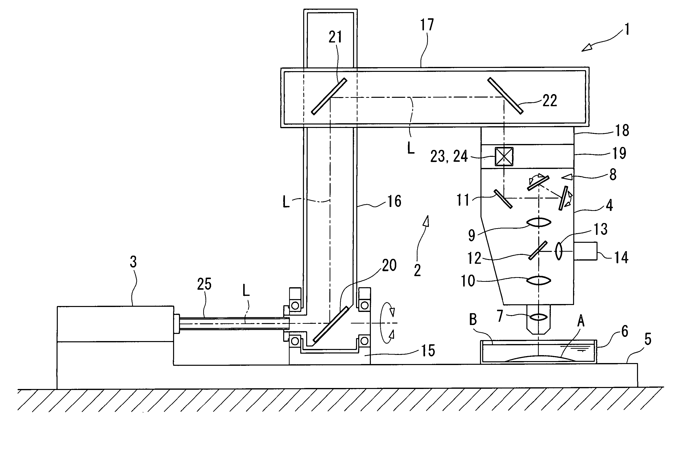
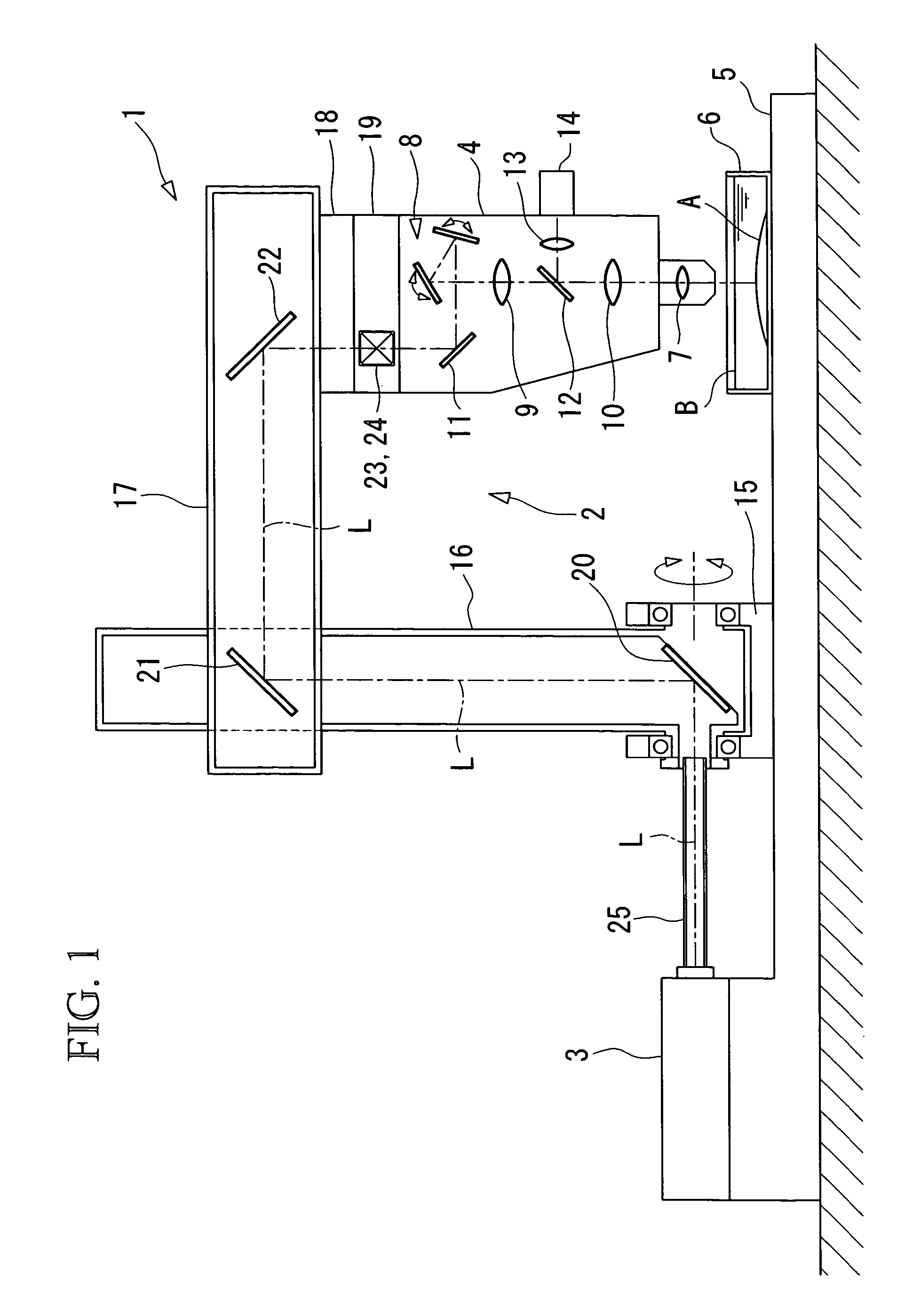
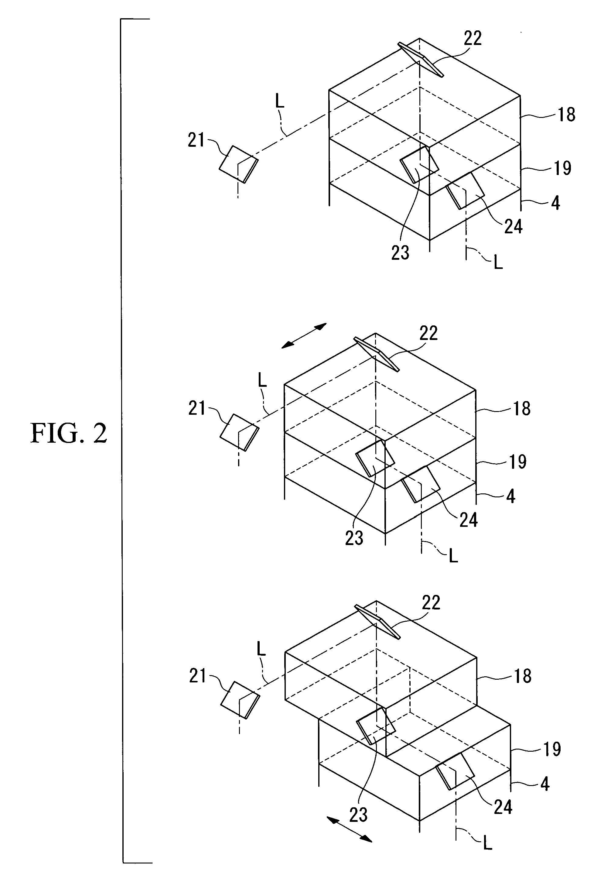
[0046] A microscope apparatus 1 and a moving unit (microscope moving unit) 2 according to a first embodiment will be described below with reference to FIGS. 1 and 2.

[0047] As shown in FIG. 1, the microscope apparatus 1 according to this embodiment includes a laser light source 3, a microscope main body 4 for observing light emitted from a specimen A when a laser beam L is incident on the specimen A, and the moving unit 2 for making the laser beam L from the laser light source 3 enter the microscope main body 4.

[0048] The laser light source 3 is an ultrashort pulse laser light source, e.g., a titanium sapphire laser, capable of generating a near-infrared pulsed laser beam having a pulse width of about 100 femtoseconds (fs) and a wavelength of about 800 nm. The laser light source 3 is fixed to a substantially horizontal base plate 5 and emits a laser beam L in a horizontal direction. A cylindrical cover 25 capable of transmitting the laser beam L is provided.

[0049] The specimen A, ...


PUM


Abstract

A microscope moving unit is provided, the microscope moving unit being capable of preventing an increase in size and a decrease in operation speed of a microscope apparatus by reducing the size of the movable parts, improving the operability of the objective lens by providing a large space around the objective lens, and allowing a specimen to be observed at various positions without affecting the specimen. The microscope moving unit includes an arm that is rotatable around an optical axis of a laser beam guided from a laser light source and that supports a microscope main body on the side closer to a tip of the arm, the microscope main body having an objective lens, and a rotatable deflecting member, which is fixed to the arm, configured to deflect the laser beam and emit the deflected laser beam towards the microscope main body at the side closer to the tip of the arm.

Description

BACKGROUND OF THE INVENTION [0001] 1. Field of the Invention [0002] The present invention relates to microscope moving units and microscope apparatuses. [0003] This application is based on Japanese Patent Application Nos. 2005-242360 and 2005-242361, the content of which is incorporated herein by reference. [0004] 2. Description of Related Art [0005] Microscope apparatuses of the related art are used to observe a specimen by moving an objective lens close to the specimen, which is placed on a stage. [0006] The stage of such a known microscope apparatus is movable horizontally in two directions (X and Y directions). To observe different areas on the specimen, the stage is operated to move the specimen in a direction that brings to be observed to a position where it intersects with the optical axis of the objective lens. [0007] However, if the specimen placed on the stage is, for example, a living cell floating in a culture medium, the specimen will be accelerated by the movement of t...

Claims


Application Information

Patent Timeline
Patent Type & Authority Applications(United States)
IPC IPC(8): G02B21/00
CPCG02B21/082G02B21/002
Inventor HONDA, SUSUMUKAWANO, YOSHIHIRO
Owner OLYMPUS CORP
Why Eureka
Try Eureka