
Adaptive estimation and compensation of clock drift in acoustic echo cancellers

a clock drift and echo canceller technology, applied in the field of clock drift compensation, can solve problems such as the end user's perception of echo or audible distortion

Inactive Publication Date: 2007-03-01
MICROSOFT TECH LICENSING LLC
View PDF1 Cites 57 Cited by
  • Summary
  • Abstract
  • Description
  • Claims
  • Application Information

AI Technical Summary

Benefits of technology

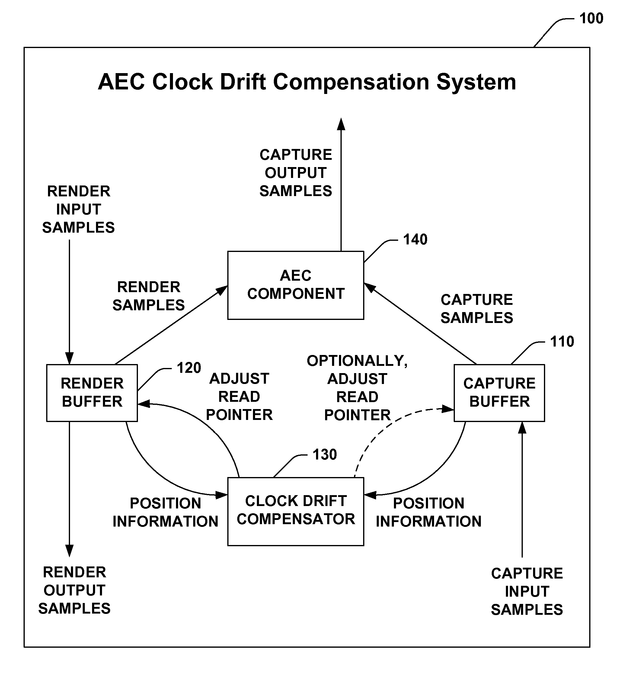
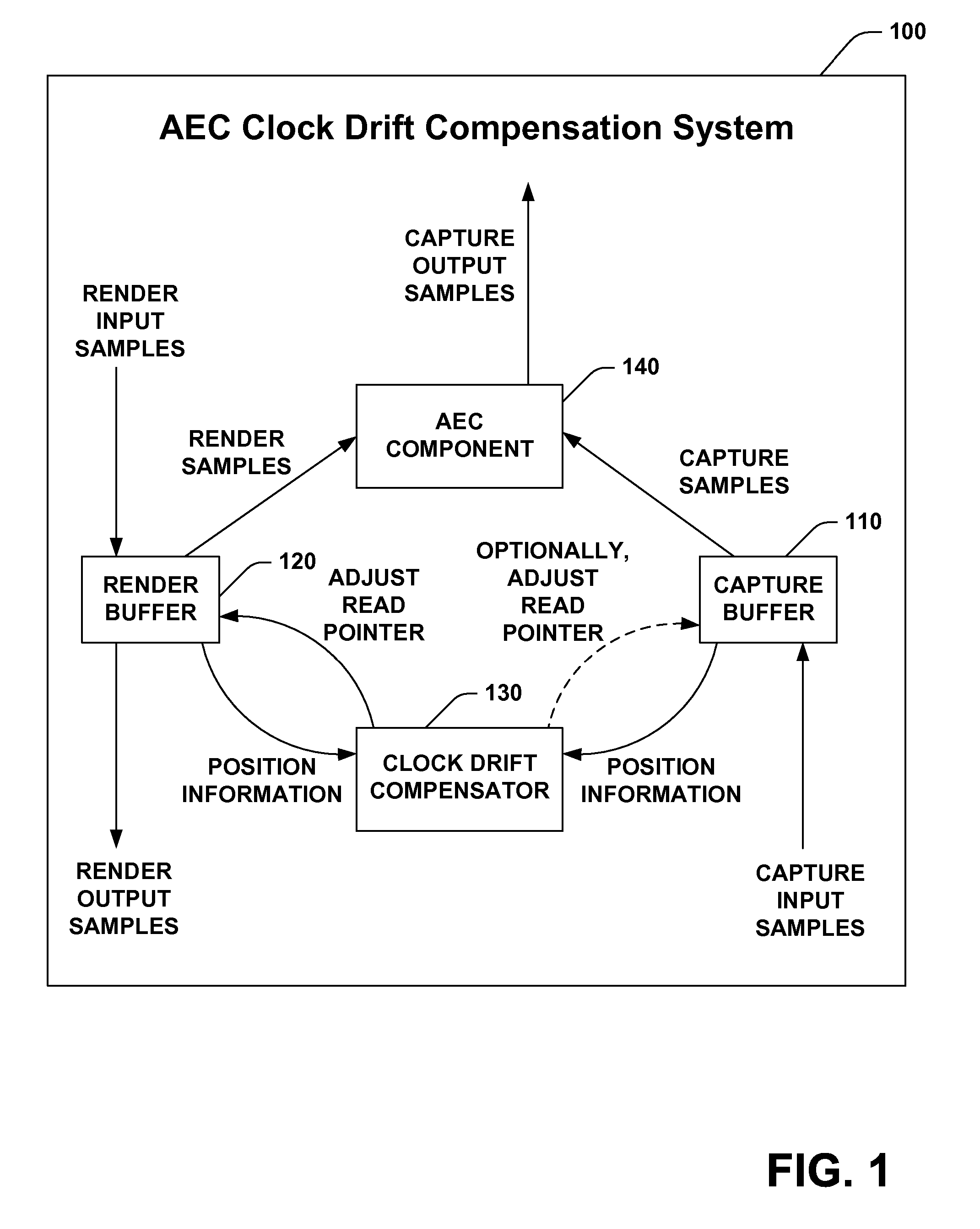
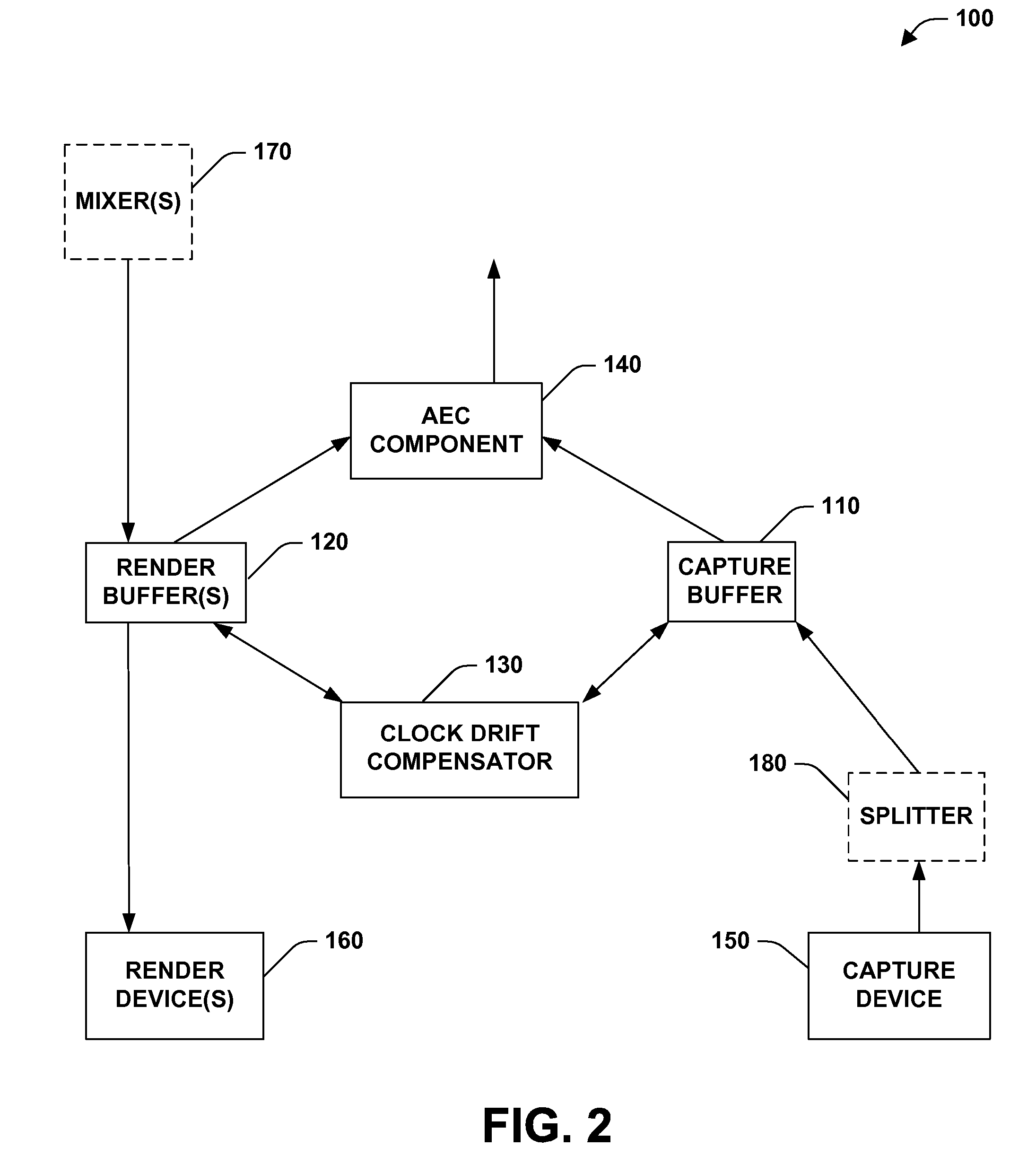
The present invention provides a system for adaptive estimation and compensation of clock drift in echo cancellers. The system includes a capture buffer, a render buffer, a clock drift compensator, and an AEC component utilizing an AEC algorithm. The system compensates for clock drift between a render device and a capture device by adjusting the render information sent to the AEC component. The system can be used in applications such as video conferencing and speech recognition engines to reduce echo due to acoustic feedback from a speaker. The system calculates a capture delay and a render offset and adjusts the render read pointer accordingly to perform acoustic echo cancellation. The system includes means for buffering capture data and render data, compensating for clock drift, and performing acoustic echo cancellation. The technical effects of the invention include improved echo cancellation and reduced audible distortion for the end user.

Problems solved by technology

Failed or lost convergence of the adaptive filter may result in the perception of echo or audible distortion by the end user.
This clock drift can cause problem(s) for the AEC algorithm attempting to adaptively model the impulse response of the room since render information provided to the AEC algorithm would not generally stay synchronized to the capture information received from the capture driver.

Method used


Image

  • Adaptive estimation and compensation of clock drift in acoustic echo cancellers
  • Adaptive estimation and compensation of clock drift in acoustic echo cancellers
  • Adaptive estimation and compensation of clock drift in acoustic echo cancellers

Examples


Embodiment Construction

[0038] The present invention is now described with reference to the drawings, wherein like reference numerals are used to refer to like elements throughout. In the following description, for purposes of explanation, numerous specific details are set forth in order to provide a thorough understanding of the present invention. It may be evident, however, that the present invention may be practiced without these specific details. In other instances, well-known structures and devices are shown in block diagram form in order to facilitate describing the present invention.

[0039] As used in this application, the term “computer component” is intended to refer to a computer-related entity, either hardware, a combination of hardware and software, software, or software in execution. For example, a computer component may be, but is not limited to being, a process running on a processor, a processor, an object, an executable, a thread of execution, a program, a driver, and / or a computer. By way...


PUM


Abstract

A system and method for adaptive estimation and compensation of clock drift in echo cancellers is provided. The invention includes an acoustic echo cancellation system with a built in adaptive clock drift compensation system. The acoustic echo cancellation system has an AEC component that performs acoustic echo cancellation on data from a capture buffer, by also using information derived from a render buffer. The clock drift compensation system has access to this capture buffer and render buffer. The clock drift compensation system includes a clock drift compensator that calculates, based on the current location of the capture data being processed by the AEC component as well as additional information, the ideal location in the render buffer from which the AEC component should process data. The clock drift compensator further adjusts the current location in the render buffer from which the AEC component processes data based, at least in part, upon this ideal location. The clock drift compensator can further detect and correct for glitches in the hardware positions received from the render and capture devices.

Description

CROSS-REFERENCE TO RELATED APPLICATIONS [0001] This application is a Continuation of U.S. patent application Ser. No. 10 / 159,075, filed May 31, 2002, and entitled, “ADAPTIVE ESTIMATION AND COMPENSATION OF CLOCK DRIFT IN ACOUSTIC ECHO CANCELLERS.” The entirety of the aforementioned application is incorporated herein by reference.TECHNICAL FIELD [0002] The present invention relates generally to clock drift compensation, and more particularly to a system and method for adaptive estimation and compensation of clock drift in acoustic echo cancellers. BACKGROUND OF THE INVENTION [0003] Acoustic echo is a common problem with full duplex audio systems, for example, audio conferencing systems and / or speech recognition systems. Acoustic echo originates in a local audio loop back that occurs when an input transducer, such as a microphone, picks up audio signals from an audio output transducer, for example, a speaker, and sends it back to an originating participant. The originating participant ...

Claims


Application Information

Patent Timeline
Patent Type & Authority Applications(United States)
IPC IPC(8): H04B3/20
CPCH04B3/493H04M9/082
Inventor BALLANTYNE, JOSEPH COXSTOKES, JACK WILSON IIIMALVAR, HENRIQUE S.
Owner MICROSOFT TECH LICENSING LLC
Learn More