
Apparatus and method of local oscillator leakage cancellation

a technology of local oscillator and leakage cancellation, which is applied in the direction of digital transmission, secret communication, baseband system details, etc., can solve the problems of increased design, manufacturing and operating costs of the transmitter, and the loss of the output signal of the transmitter, so as to improve the reduction or elimination of the lo leakage signal

Inactive Publication Date: 2007-03-01
AVAGO TECH INT SALES PTE LTD
View PDF12 Cites 4 Cited by
  • Summary
  • Abstract
  • Description
  • Claims
  • Application Information

AI Technical Summary

Benefits of technology

[0007] Accordingly, the present invention provides improved reduction or elimination of a LO leakage signal in a transmitter output signal caused by baseband DC offsets.
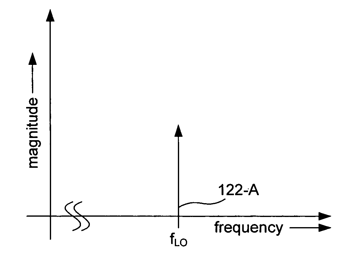
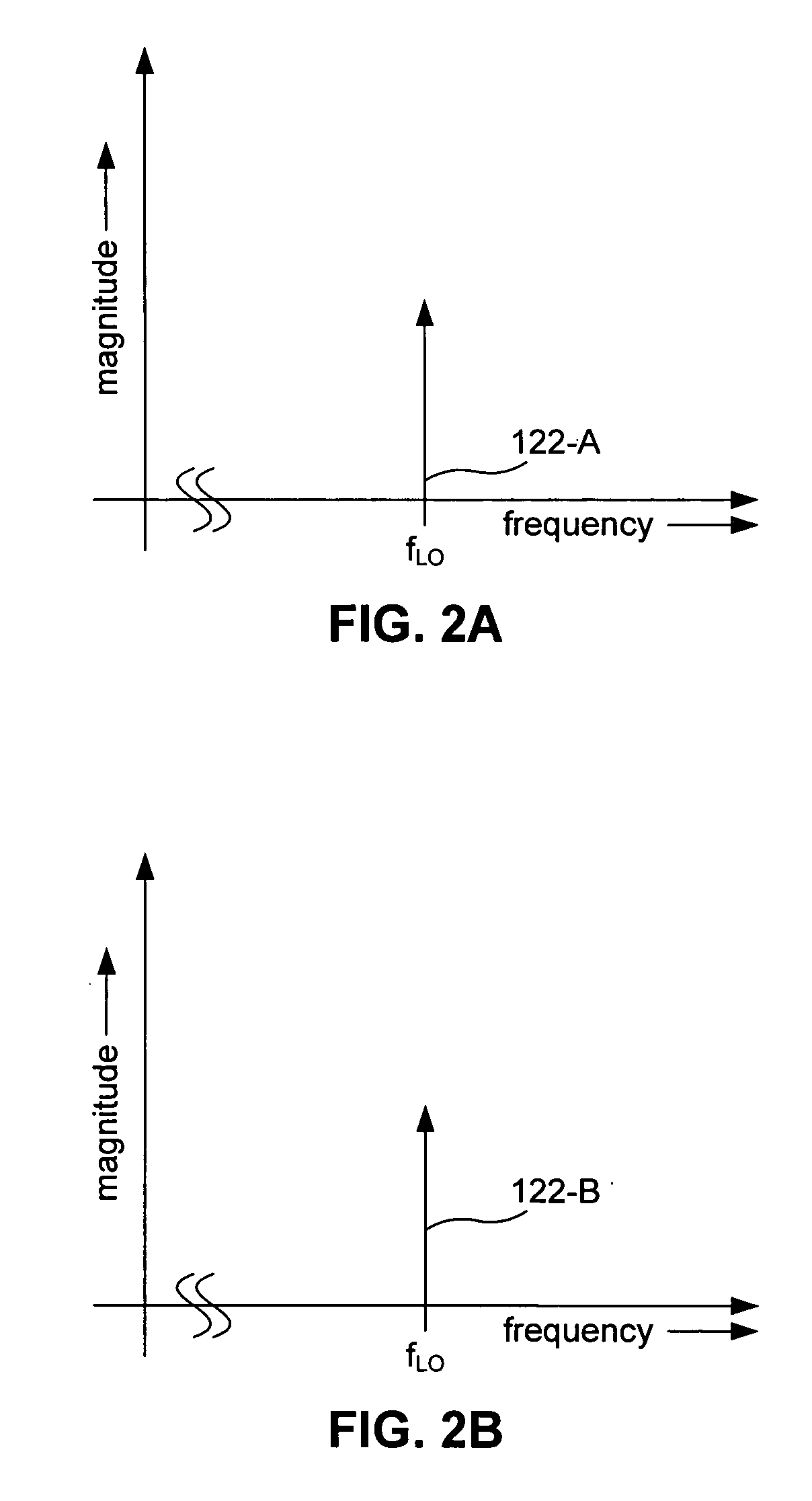
[0008] In one embodiment, a transmitter includes a first mixer to generate a first output signal by up-converting a first baseband signal having a first DC offset component. A second mixer generates a second output signal by up-converting a second baseband signal having a second DC offset component. The second output signal is subtracted from the first output signal to generate a transmitter output signal. The transmitter output signal includes a local oscillator (LO) leakage signal caused by the first and / or second DC offset components. A first filter filters the first baseband signal to isolate the first DC offset component. A third mixer produces a third output signal by up-converting the first DC offset component provided by the first filter. A second filter filters the second baseband signal to isolate the second DC offset component. A fourth mixer produces a fourth output signal by up-converting the second DC offset component provided by the second filter. The fourth output signal is subtracted from the third output signal to generate a LO leakage cancellation signal. The LO leakage cancellation signal is subtracted from the transmitter output signal, thereby reducing a power of the LO leakage signal.
[0009] In another embodiment, there is provided a method for reducing a power of a LO leakage signal in a transmitter output signal. A transmitter output signal is generated from one or more baseband signals. At least one of the one or more baseband signals includes a DC offset component. The transmitter output signal includes a LO leakage signal component caused by each DC offset component. A LO leakage cancellation signal is generated from each DC offset components. The LO leakage cancellation signal is subtracted from the transmitter output signal. Consequently, the power of the LO leakage signal is reduced or eliminated.

Problems solved by technology

The LO leakage signal is an undesirable signal that can interfere with the subsequent detection and demodulation of the transmitter output signal.
The quality of the transmitter output signal suffers if a transmitter fails to compensate for the baseband DC offset component of a LO leakage signal.
Such calibration circuits are often expensive in terms of required processing power and required additional components.
Consequently, design, manufacturing and operating costs of the transmitter are increased.

Method used


Image

  • Apparatus and method of local oscillator leakage cancellation
  • Apparatus and method of local oscillator leakage cancellation
  • Apparatus and method of local oscillator leakage cancellation

Examples


Embodiment Construction

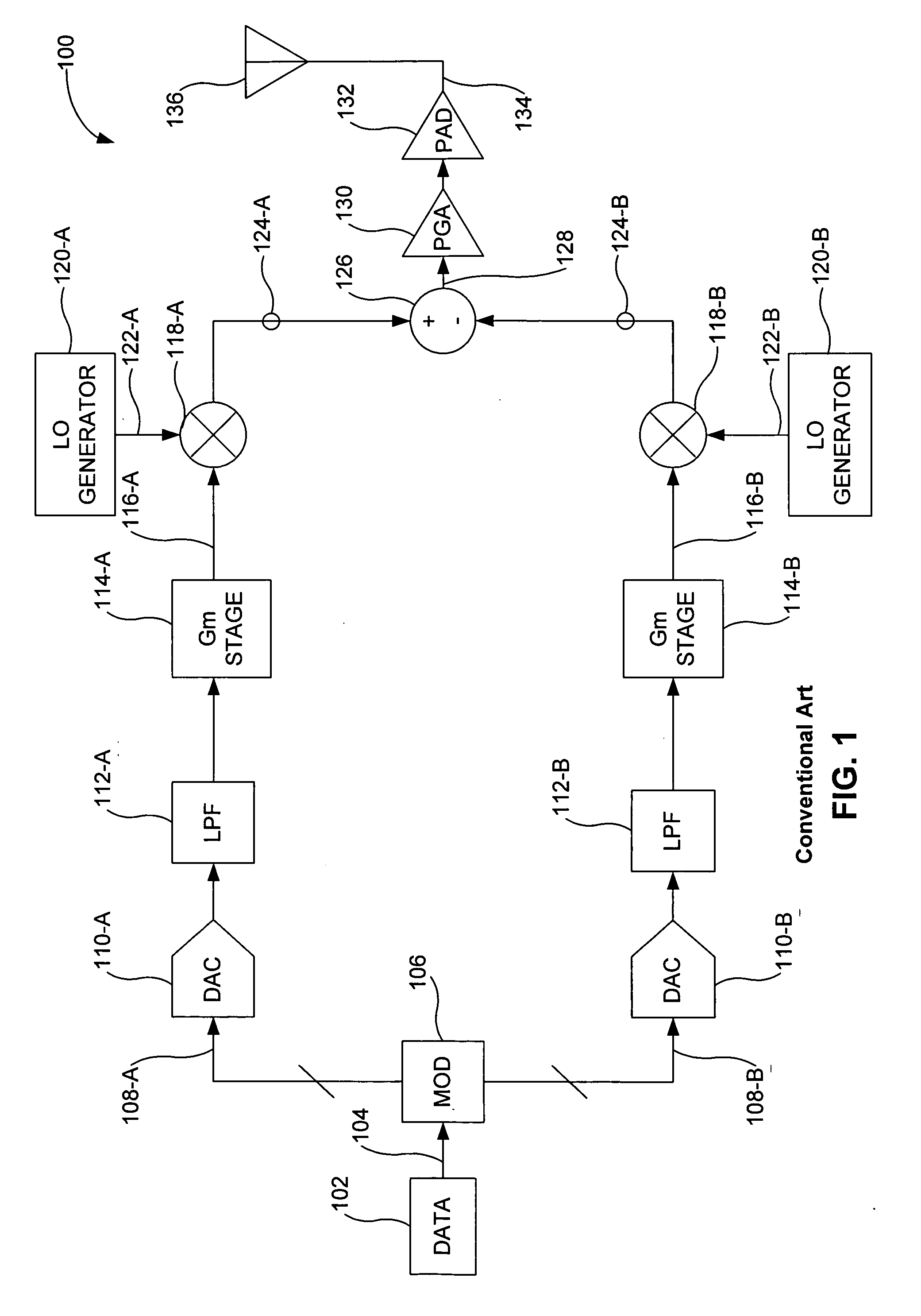
[0026]FIG. 1 illustrates a conventional wireless transmitter 100. The conventional wireless transmitter 100 includes an information source 102. The information source 102 generates a data signal 104. The data signal 104 is a sequence of bits. The information source 102 provides the data signal 104 to a modulator 106. The modulator 106 encodes and modulates the data signal 104 and provides two modulation channels (e.g., an in-phase channel and a quadrature-phase channel). Specifically, the modulator 106 generates a modulated data signal 108-A and an associated modulated data signal 108-B. The modulated data signals 108-A and 108-B can be baseband signals or can be signals centered at an intermediate frequency (IF). The modulated data signals 108-A and 108-B can be considered to be in-phase and quadrature-phase information signals, respectively. At the output of the modulator 106, the modulated data signals 108-A and 108-B are multiple-bit digital signals.

[0027] As illustrated in FIG...


PUM


Abstract

A transmitter includes a first mixer to generate a first output signal by up-converting a first baseband signal having a first DC offset component. A second mixer generates a second output signal by up-converting a second baseband signal having a second DC offset component. The second output signal is subtracted from the first output signal to generate a transmitter output signal. The transmitter output signal includes a local oscillator (LO) leakage signal caused by the first and / or second DC offset components. A third mixer produces a third output signal by up-converting the first DC offset component. A fourth mixer produces a fourth output signal by up-converting the second DC offset component. The fourth output signal is subtracted from the third output signal to generate a LO leakage cancellation signal. The LO leakage cancellation signal is subtracted from the transmitter output signal, thereby reducing a power of the LO leakage signal.

Description

BACKGROUND OF THE INVENTION [0001] 1. Field of the Invention [0002] The present invention generally relates to local oscillator (LO) leakage signal reduction. More specifically, the present invention provides LO leakage signal cancellation using baseband DC offsets. [0003] 2. Background Art [0004] Generally, a wireless radio frequency (RF) transmitter includes a baseband section and an RF section. Baseband information signals are generated and manipulated within the baseband section. The baseband information signals are up-converted and further manipulated within the RF section to produce a transmitter output signal. [0005] Random device mismatches within the constituent components of the baseband section can produce DC offsets within the baseband information signals. These baseband DC offsets can be up-converted by the transmitter to produce a LO leakage signal. The LO leakage signal is an undesirable signal that can interfere with the subsequent detection and demodulation of the t...

Claims


Application Information

Patent Timeline
Patent Type & Authority Applications(United States)
IPC IPC(8): H04B1/04H01Q11/12
CPCH04B1/0475H03D2200/009
Inventor PAN, MENG-AN
Owner AVAGO TECH INT SALES PTE LTD
Learn More