Ink tank and recording apparatus

a technology of recording apparatus and ink tank, which is applied in the field of ink tank and recording apparatus, can solve the problems of excessive dark image formation, insufficient dye ink performance, and limited width of each ink tank, and achieves the effect of efficient stirring ink and high quality

Active Publication Date: 2007-03-08
CANON KK
View PDF0 Cites 12 Cited by
  • Summary
  • Abstract
  • Description
  • Claims
  • Application Information

AI Technical Summary

Benefits of technology

[0017] The present invention is directed to an ink tank configured to efficiently stir ink stored inside the ink tank and a recording apparatus configured to form high quality images by using ink having a uniform concentration.

Problems solved by technology

However, the performance of dye ink is not sufficient when used for recording images on a recording medium to be displayed outdoors because, when displaying an image outdoors, it is important for the ink to have good light resistance and good whether resistance.
However, when pigment ink is used, the pigment particles are deposited at the bottom of the ink tank because pigment ink forms a dispersal system, not a soluble system.
If the ink inside the ink tank is guided outside through the bottom of the ink tank and supplied to a recording head, first, the ink in the highly concentrated pigment layer is supplied, causing an excessively dark image to be formed.
However, the ink tanks described in Japanese Patent Laid-Open No. 2004-216761 have the following problems.
However, since a plurality of ink tanks is often mounted on the carriage along the direction of the carriage's movement, the width of each ink tank is limited to a relatively small width.
For this reason, the shaking range of the stirrer cannot be increased, and, thus, the ink flow generated by the shaking of the stirrer cannot be increased.
However, for the former ink tank, it is difficult to sufficiently stir the entire volume of ink, including the ink close to the upper surface of the ink tank, by merely moving the weight provided at the bottom of the ink tank.
Furthermore, both of the ink tanks do not effectively operate unless structures allowing air to be taken in to the ink storage unit in accordance with the decrease in the volume of ink are provided.
However, some ink tanks have structures that do not allow air to be taken in.
Therefore, there is not enough space (air) for the ink to move inside the ink tank.
Accordingly, it is difficult to generate a strong flow of ink by reciprocating the carriage and / or moving a spherical weight.
These problems in the ink tank described in Japanese Patent Laid-Open No. 2004-216761 are also apparent from the structure of a typical ink tank and recording apparatus described below.
Accordingly, the ink-stirring efficiency is reduced, and a great amount of time will be required to stir the entire volume of ink in the ink tank.
As a result, the warm-up time required for enabling a recording operation will become long.
Therefore, a concentration distribution causing negative effects on the image formed by the recording apparatus may be generated inside the ink tank by merely leaving the ink tank untouched for several days.
However, while the ink is being stirred, image formation cannot be carried out.

Method used


Image

  • Ink tank and recording apparatus
  • Ink tank and recording apparatus
  • Ink tank and recording apparatus

Examples


first embodiment

[0039] (Structure of Recording Apparatus)

[0040]FIGS. 13 and 14 illustrate example structures of an inkjet recording apparatus according to an embodiment of the present invention.

[0041] As shown in FIG. 13, an inkjet recording apparatus according to this embodiment includes a main body M1000, a supplying unit M3022, and an eject tray M1004. As shown in FIG. 14, the main body M1000 includes a chassis M3019 and a recording mechanism. The recording mechanism includes a carriage M4001 capable of reciprocating in a primary scanning direction indicated by the arrow A. The carriage M4001 holds an ink tank for storing ink and an inkjet recording head capable of discharging the ink stored in the ink tank from a plurality of ink outlets. The ink tank and the recording head may constitute a single unit, i.e., ink cartridge, or, instead, the ink tank may be detachable from the recording head. The recording head, for example, discharges ink using electrothermal conversion bodies (i.e., heaters)...

second embodiment

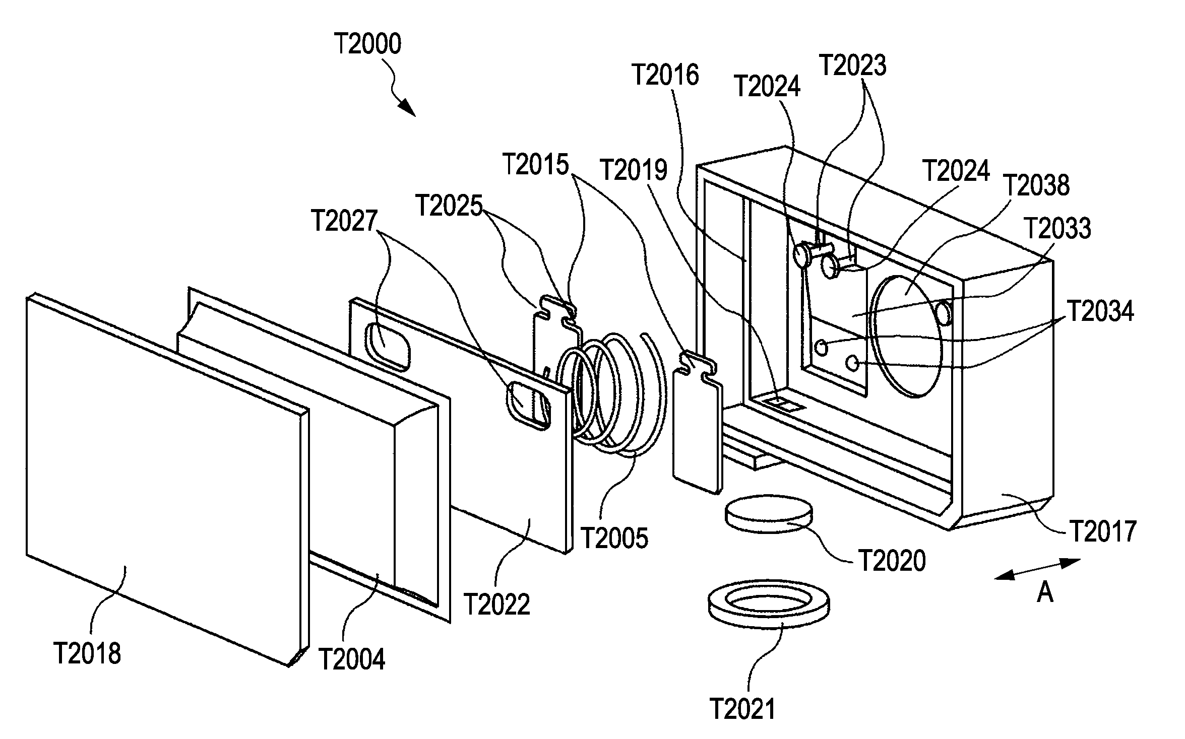
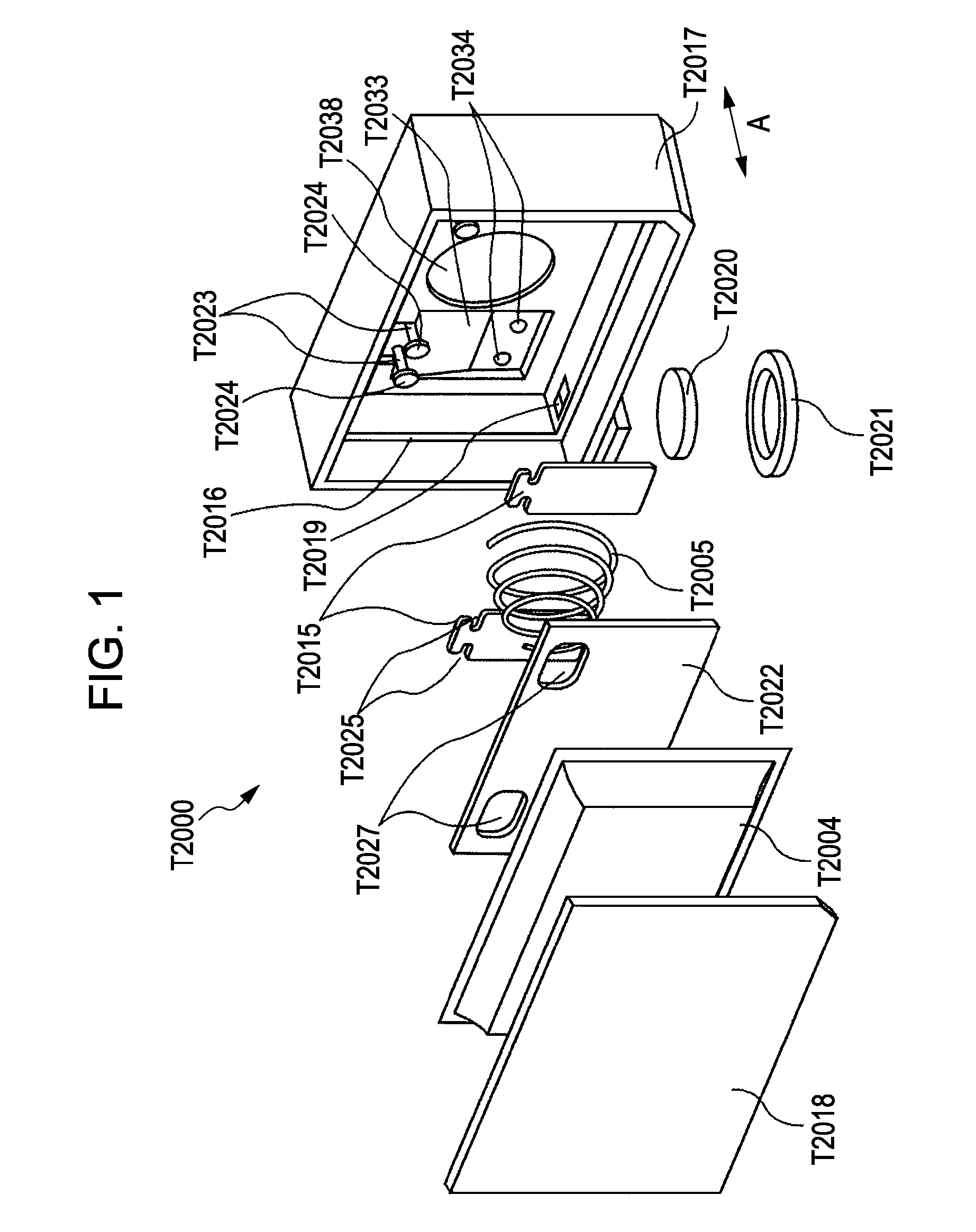
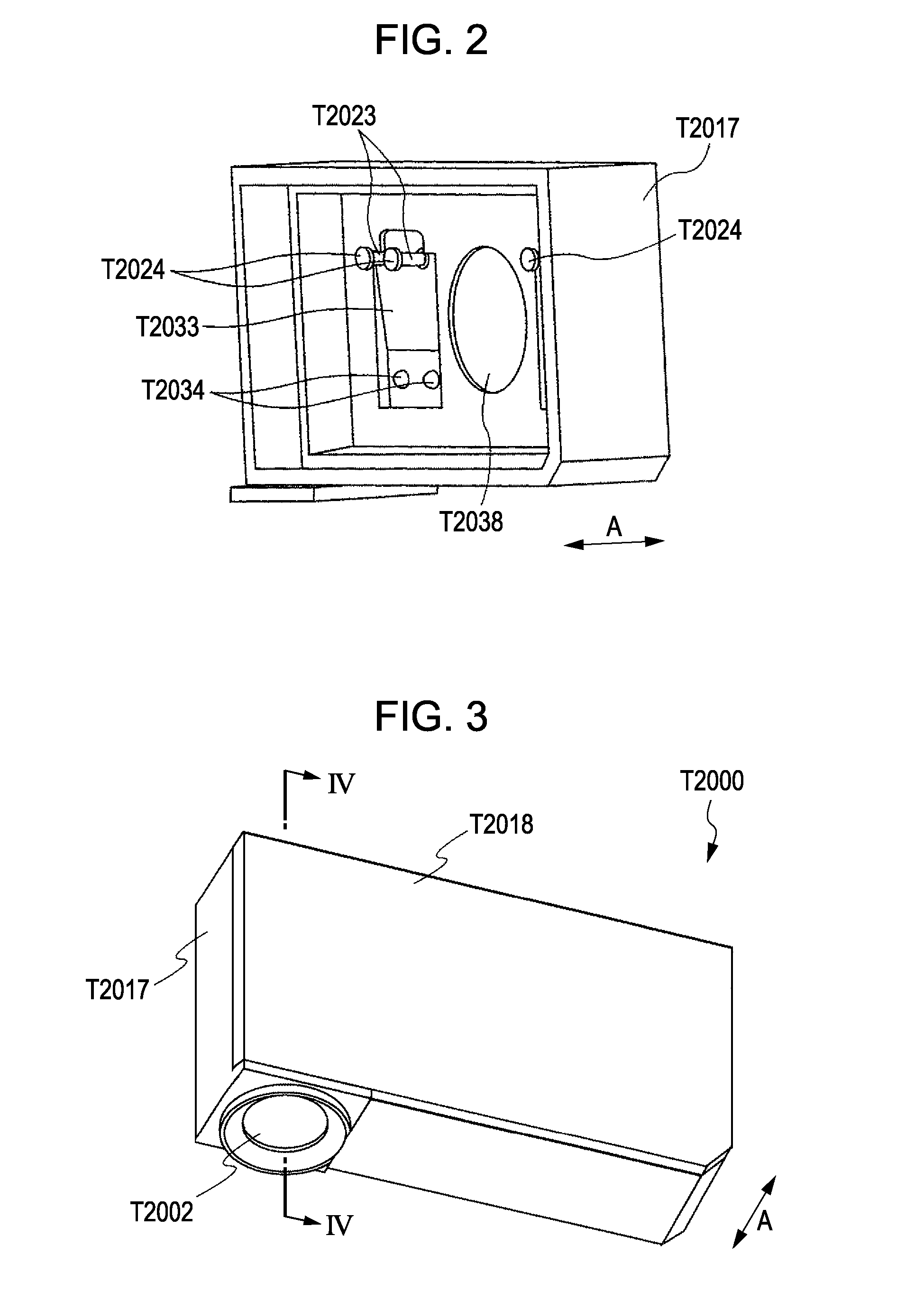
[0074] FIGS. 10 to 12 illustrate an ink tank according to a second embodiment of the present invention. The structure and movement of the stirring mechanisms of the ink tank T2000 according to the second embodiment differs from those of the ink tank according to the first embodiment to some extent. Other features of the second embodiment that are the same as those of the first embodiment, and descriptions thereof are not repeated.

[0075] (Structure of Stirring Mechanism)

[0076] Similar to the first embodiment, two ink stirring mechanisms that interpose a spring member T2005 are provided inside an ink storage chamber T2001 of the ink tank T2000. The two stirring mechanisms have identical structures and operate in the identical ways. Therefore, in the following, only one stirring mechanism will be described.

[0077]FIG. 10 is an exploded perspective view illustrating the stirring mechanism according to this embodiment.

[0078] The stirring mechanism according to this embodiment includes...


PUM


Abstract

An ink tank includes a stirrer supported in a freely moveable manner near an inner wall of an ink storage chamber. When the stirrer moves closest to the inner wall, a predetermined gap is formed between opposing surfaces of the inner wall and the stirrer.

Description

BACKGROUND OF THE INVENTION [0001] 1. Field of the Invention [0002] The present invention relates to an ink tank configured to store recording liquid, such as ink, and a recording apparatus including the ink tank. The present invention can be applied to various recording apparatuses having ink tanks. For example, the present invention can be applied to a typical printer, a copy machine, a facsimile having a communication system, a word processor having a printing unit, and an industrial recording apparatus integrated with various other processing apparatuses. [0003] 2. Description of the Related Art [0004] As a recording apparatus that uses ink stored in an ink tank, for example, an inkjet recording apparatus using an inkjet recording head for discharging ink is known. As such an inkjet recording apparatus, a serial scanning type inkjet recording apparatus that includes a carriage holding an inkjet recording head and an ink tank and moves in the primary scanning direction is known. ...

Claims


Application Information

Patent Timeline
Patent Type & Authority Applications(United States)
IPC IPC(8): B41J2/175
CPCB41J2/17513
Inventor KUBO, KOICHIKAWAMURA, SHOGOOHASHI, TETSUYAINOUE, RYOJIOGURA, HIDEKIKOTAKI, YASUO
Owner CANON KK
Why Eureka
Try Eureka