
Source-adaptive video deinterlacer

Active Publication Date: 2007-03-08
LATTICE SEMICON CORP
View PDF80 Cites 27 Cited by
  • Summary
  • Abstract
  • Description
  • Claims
  • Application Information

AI Technical Summary

Benefits of technology

[0014] The proposed method and device can offer, among other advantages, improved quality of deinterlaced video. This can be accomplished in an efficient and robust manner compared to other deinterlacing techniques because a cadence can be detected independent of the source. These and other advantages of the present invention will become apparent to those skilled in the art upon a reading of the following descriptions and a study of the several figures of the drawings.

Problems solved by technology

Furthermore, deinterlacing is often required because modern televisions are inherently progressive and the video feed is broadcast in interlaced form.
While this technique maintains vertical resolution, it has the problem of creating interlace motion artifacts if motion is present.
While vertical interpolation allows a progressive picture to be generated from one video field, half of the resolution of the video feed is lost.
However, cadence detection systems are inadequate because they are generally limited to 3:2 pulldown or 2:2 pulldown.
Further cadence detection systems incur a number of problems when the cadence pattern is broken for some reason, such as video edits.
Other limitations of the related art will become apparent to those of skill in the art upon a reading of the specification and a study of the drawings.

Method used


Image

  • Source-adaptive video deinterlacer
  • Source-adaptive video deinterlacer
  • Source-adaptive video deinterlacer

Examples


Embodiment Construction

[0029] In the following description, several specific details are presented to provide a thorough understanding of embodiments of the invention. One skilled in the relevant art will recognize, however, that the invention can be practiced without one or more of the specific details, or in combination with other components, etc. In other instances, well-known implementations or operations are not shown or described in detail to avoid obscuring aspects of various embodiments, of the invention.

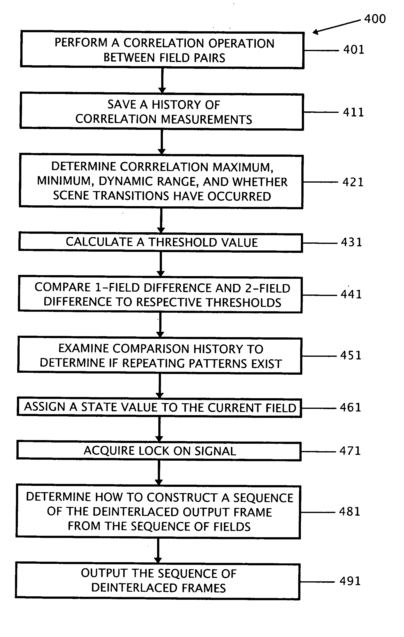
[0030] A method is described for source adaptive deinterlacing of an interlaced video signal to create a progressive video signal. As described further below, the method includes determining if a sequence of two or more fields from the interlaced source is derived from the same original progressive source frame. One method of determining if a sequence of two fields have a common source is to determine how similar the two fields are to each other. The more similar the two fields are to each other,...


PUM


Abstract

A method is described for deinterlacing an interlaced video stream. The method includes detecting an occurrence of groups of adjacent fields that are derived from a common original image frame source, and merging field pairs of the interlaced video stream to create a non-interlaced video stream output.

Description

CROSS-REFERENCE TO RELATED APPLICATION [0001] This Application claims the benefit of United States Provisional Application No. 60 / 715,711 entitled “Source-Adaptive Video Deinterlacer,” filed on Sep. 8, 2005, which is incorporated by reference.BACKGROUND [0002] Interlaced scanning and progressive scanning are typical scanning methods employed in a video display device. Interlaced scanning has been employed in current National Television Systems Committee (“NTSC”) television (“TV”) systems. For the video display shown in FIGS. 1A-1C, even and odd fields would be interlaced sequentially and alternately on the screen when displaying a video image. For FIGS. 1A-1C, for interlaced scanning, the solid lines would represent lines being scanned at present, and the dotted lines would represent lines scanned for a preceding display. [0003] Deinterlacing an interlaced signal provides numerous advantages for improving video quality. Specifically, deinterlacing can remove interlace motion artifac...

Claims


Application Information

Patent Timeline
IPC IPC(8): H04N7/01
CPCH04N7/0112H04N7/0147H04N7/012H04N11/20
Inventor ADAMS, DALE RICHARD
Owner LATTICE SEMICON CORP
Learn More