Gantry for a computed tomography apparatus and method for cooling a gantry

Active Publication Date: 2007-03-08
SIEMENS HEALTHCARE GMBH
View PDF2 Cites 10 Cited by
  • Summary
  • Abstract
  • Description
  • Claims
  • Application Information

AI Technical Summary

Benefits of technology

[0009] The present invention is to provide a gantry for a computed tomography apparatus wherein the noise stress in the operation of the gantry is reduced.

Problems solved by technology

Given identical intervals between the openings and identical opening geometry a very low-frequency, uncomfortable disruptive noise results.
This leads to a “smeared” noise which is not as uncomfortable to the h

Method used


Image

  • Gantry for a computed tomography apparatus and method for cooling a gantry
  • Gantry for a computed tomography apparatus and method for cooling a gantry
  • Gantry for a computed tomography apparatus and method for cooling a gantry

Examples


Example

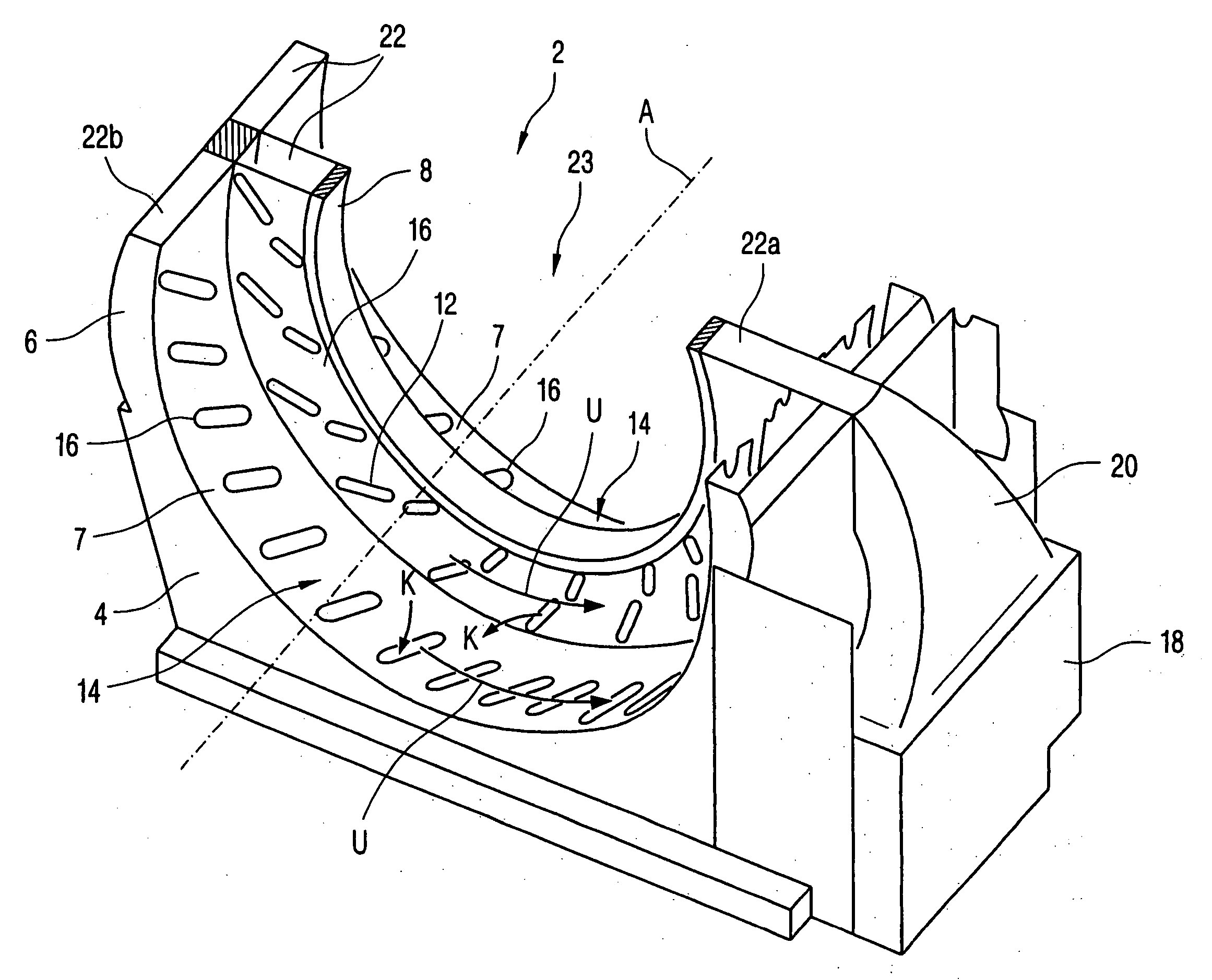
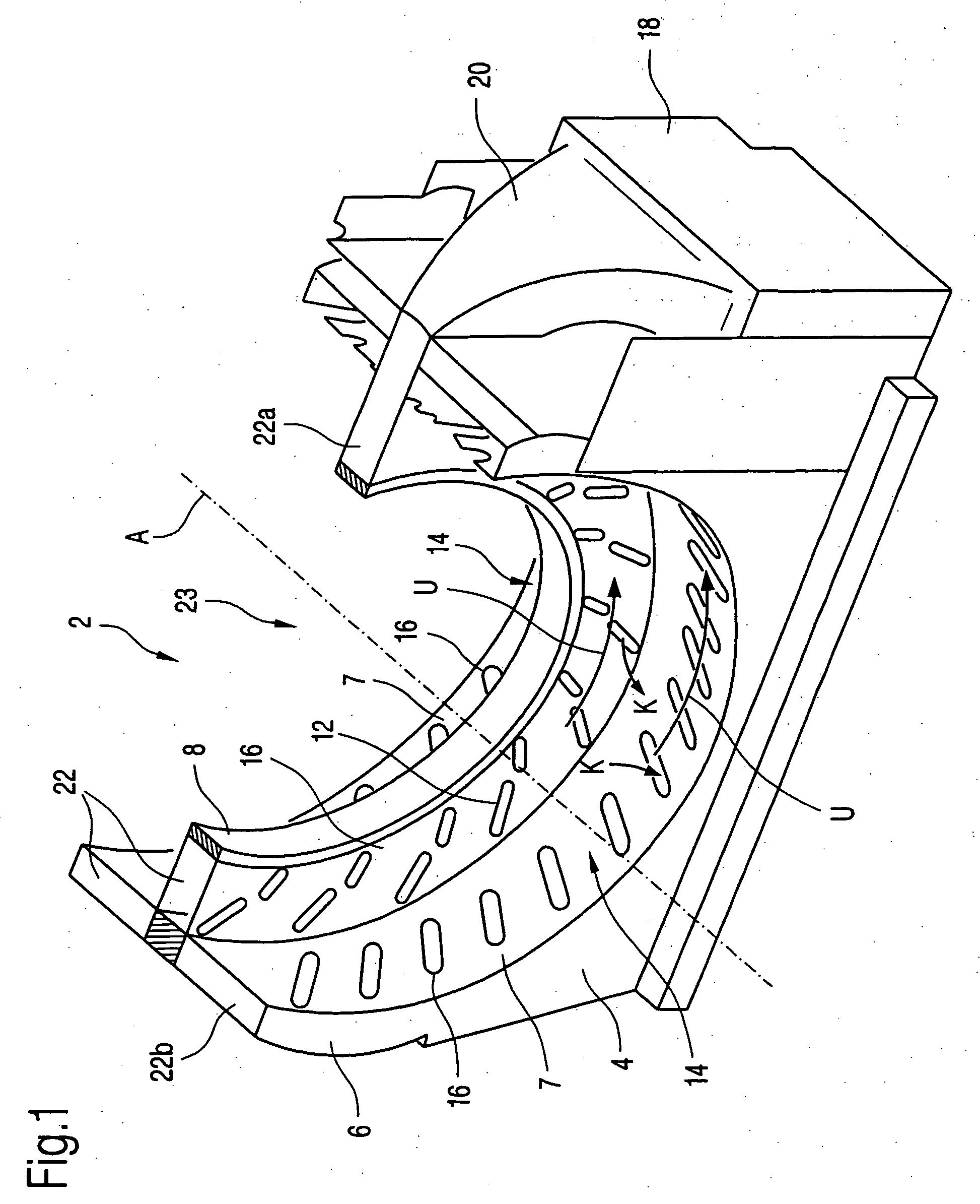
[0032]FIG. 1 is a perspective view of a part of a computed tomography apparatus 2. The computed tomography apparatus 2 has a supporting body 4 that exhibits a cavity and the lower half of a support ring 6. The supporting body 4 and the support ring 6 are fashioned in one piece and integrated with one another. The support ring 6 is arranged rotationally symmetric around an axis A that indicates its axial direction. The support ring 6 comprises a cooling ring 8 oriented in the radial direction on its radially-inward circumferential side 7. Both flanks 10 of the cooling ring 8 are provided with outlets 12 that form two rows in the circumferential direction U. The cooling ring 8 exhibits a smaller axial extent than the support ring 6 and is centrally positioned on the support ring 6 such that two approximately equally large cooling spaces 14 are formed on both sides of the cooling ring. On both sides of the cooling ring 8 each circumferential side 7 exhibits a row of suction openings 16...


PUM


Abstract

A gantry for a computed tomography apparatus has a rotary carriage that is rotatable around an axis and a support ring arranged around the rotary carriage with a circumferential cooling channel. The support ring has a number of openings distributed around its circumference and forming a non-uniform opening pattern. The rotary carriage likewise has inflow and outflow openings that, in operation, overlap the openings on the stationary part of the computed tomography apparatus such that a coolant flows through between the support ring and the rotary carriage. A steady pressure fluctuation that leads to a reduction of the noise stress in operation ensues thanks to the non-uniform opening pattern.

Description

BACKGROUND OF THE INVENTION [0001] 1. Field of the Invention [0002] The present invention concerns a gantry for a computed tomography apparatus of the type having a rotary carriage that is rotatable around an axis and a support ring arranged around the rotary carriage with a circumferential cooling channel. The invention furthermore concerns a computer tomograph having such a gantry and a method for cooling such a gantry. [0003] 2. Description of the Prior Art [0004] In a computed tomography apparatus three-dimensional slice images of the inside of a patient are generated by x-ray imaging method. For this purpose, two-dimensional x-ray slice images, from which a three-dimensional slice image is reconstructed, are generated by a scanning unit that normally includes an x-ray radiator rotating around the acquisition subject and an image acquisition system. The computed tomography apparatus typically has a stationary part that with a support ring is arranged around a patient acquisition...

Claims


Application Information

Patent Timeline
IPC IPC(8): H01J35/10H01J35/12H05G1/60A61B6/00G01N23/00G21K1/12
CPCA61B6/4488A61B6/035
Inventor DISTLER, FRIEDRICHKRUG, RITAMULLER, HANS-JURGEN
Owner SIEMENS HEALTHCARE GMBH
Why Eureka
Try Eureka