Bone conduction speaker

Inactive Publication Date: 2007-03-08
GOLDEN DANCE
View PDF1 Cites 24 Cited by
  • Summary
  • Abstract
  • Description
  • Claims
  • Application Information

AI Technical Summary

Benefits of technology

[0007] In order to solve the above mentioned problem, instead of putting the magnets 5, 5′ near the coil 3, only one permanent magnet is mounted on top of an iron piece fixed to a vibrating plate attached to the resonator. It is therefore unnecessary to adjust the position of the magnet, which allows for enlarging the coil's and the magnet's sizes, and consequently it is possible to easily adjust the output power and to make the speaker compact and lightweight.
[0008] According to an embodiment of this invention, only one magnet is made as a single part of the speaker. Thus, it is not necessary to adjust its direction and therefore the assembling process is simplified, and the production cost can be largely reduced. Since the permanent magnet is positioned at top of the iron piece, rather than surrounding the coil, the size of the coil can be increased (t

Problems solved by technology

However, as suggested in the aforesaid invention description, the exact symmetrical placing of two rectangle prism magnets, facing each other at the two opposite sides of the coil 3 is n

Method used


Image

  • Bone conduction speaker
  • Bone conduction speaker
  • Bone conduction speaker

Examples


Example

[0018] While the invention may be susceptible to embodiment in different forms, there are shown in the drawings, and will be described in detail herein, specific embodiments of the present invention, with the understanding that the present disclosure is to be considered an exemplification of the principles of the invention, and is not intended to limit the invention to that as illustrated and described herein.

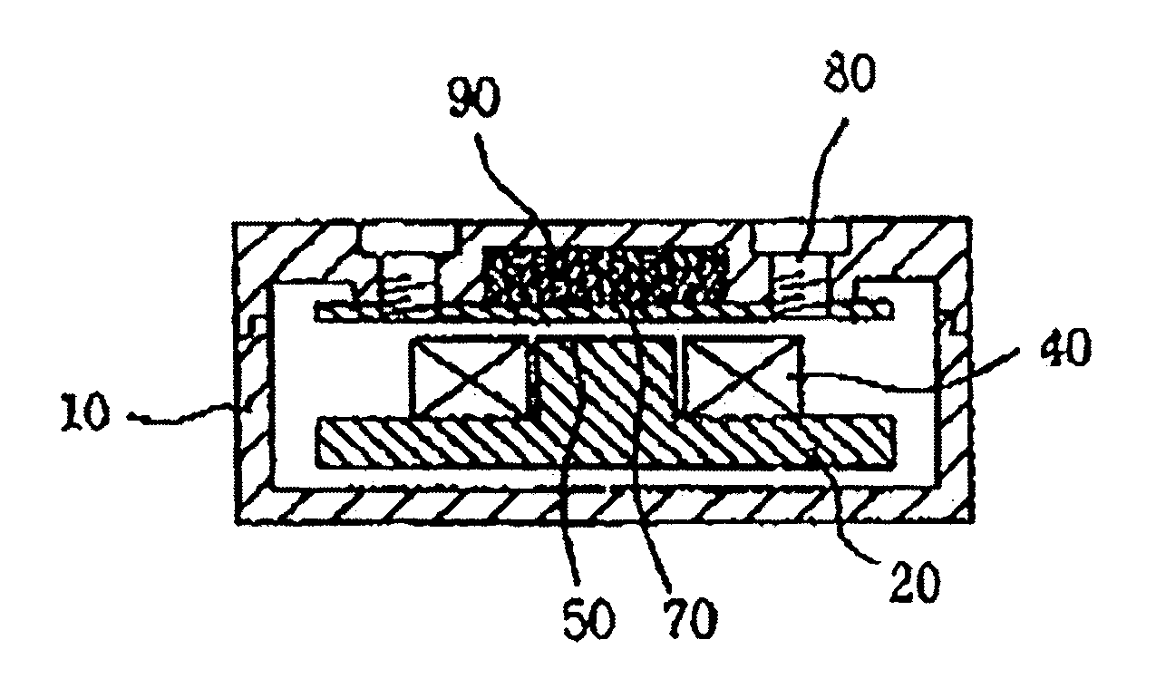
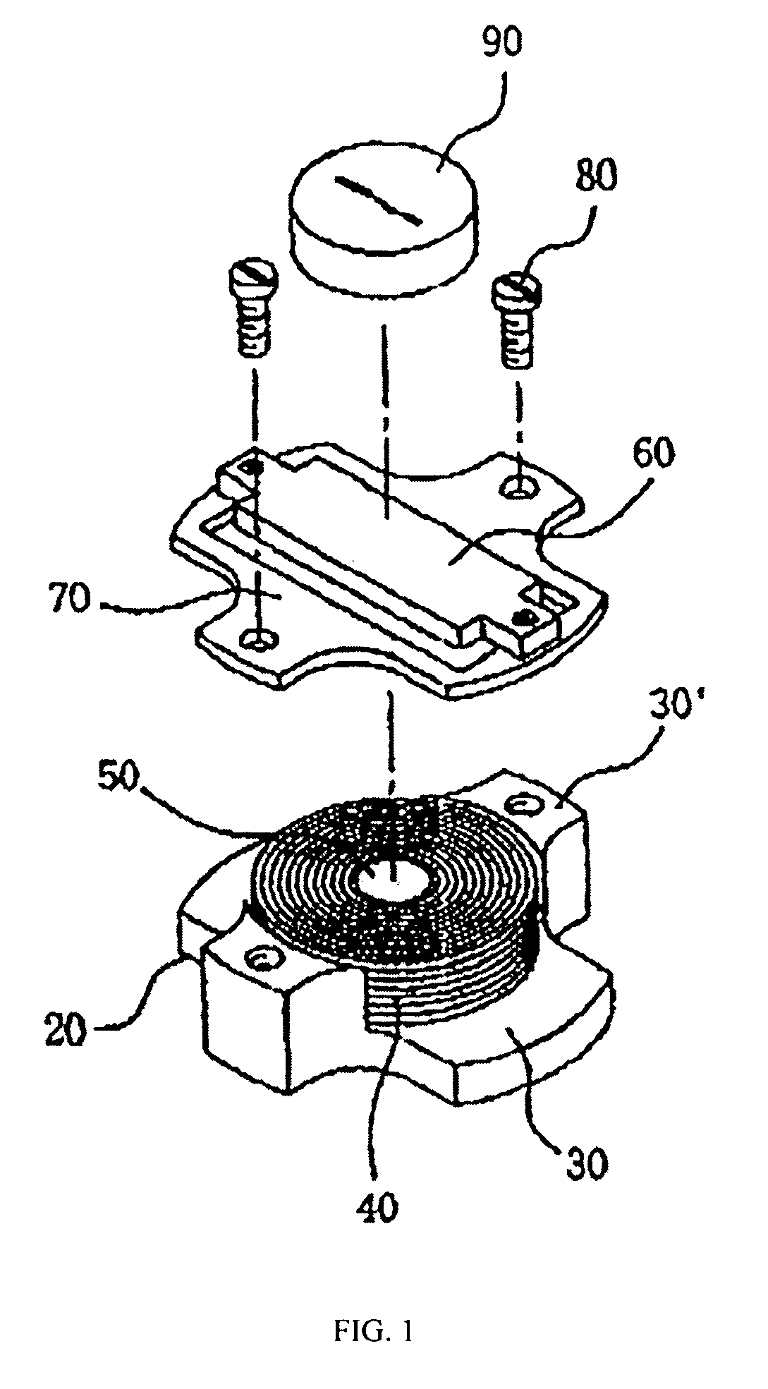
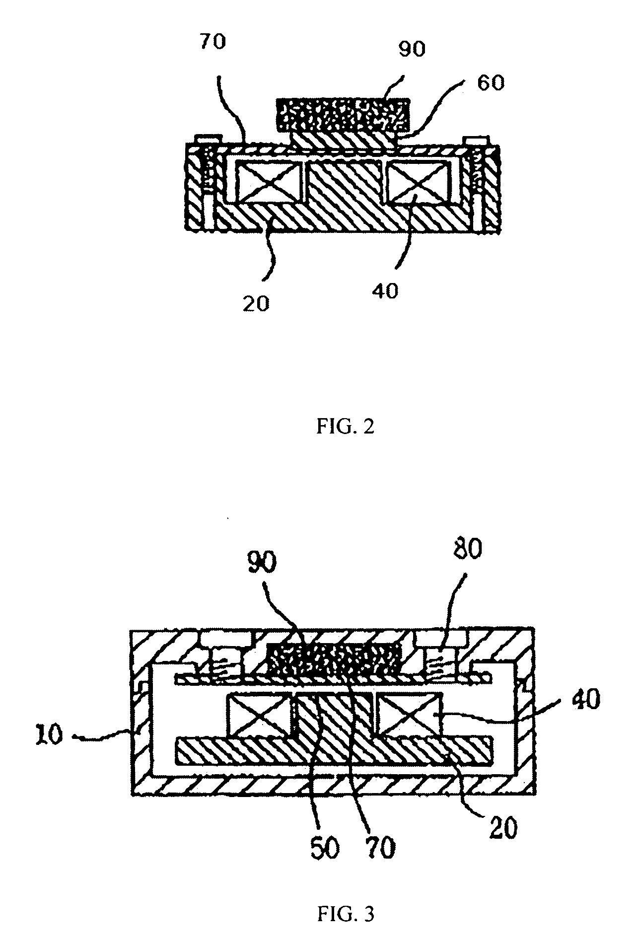
[0019] As illustrated on FIG. 1, an embodiment of the inventive speaker comprises resonator means, including a plate-shaped resonator (20) mounted in a housing (not shown in FIG. 1). The resonator 20 includes two radially extended parts 30 and two upward standing radially extended parts 30′. Each extended part 30 and 30′ has a horizontal axis preferably positioned at a right angle to the neighboring extended part's horizontal axis.

[0020] The embodiment of the inventive speaker, shown on FIG. 1, comprises electromagnetic oscillation means including a sound coil (40) and a cent...


PUM


Abstract

A bone conduction speaker is utilized for hearing aid and other devices. The speaker's structure is improved by arranging a single permanent magnet above an iron piece coupled to a vibrating plate fixed to a resonator, containing at least one sound coil, enclosing a magnetic core located substantially beneath the center of plate. Audio signals are converted into oscillating current, input in the coil that alternates attractive/repulsing forces applied to the iron piece producing vibrations of the plate amplified by the resonator, further conducted through skin and skull to auditory nerves for sound recognition. The structure allows avoiding laborious adjustments of the permanent magnet means during the assembly process, freeing the internal space of resonator, enlarging the coil and core, improving performance, making the speaker compact and lightweight, reducing production costs. An embodiment is furnished with upwards standing parts disposed at two resonator's opposite ends, forming stable structure.

Description

CROSS REFERENCE TO RELATED APPLICATIONS [0001] This application claims priority under 35 U.S.C. 119(a) through (d) from a patent application No. 20-2005-0025945 filed on 8 Sep. 2005 in Korea. BACKGROUND OF THE INVENTION [0002] The present invention relates to vibrators preferably utilized in hearing aid devices, assistive listening devices, audio and communication devices of the bone conduction type, wherein audio or other acoustic signals (sounds) are transmitted through the skull bone directly to the cochlea (inner ear) of a person, where the audio signals can be consciously recognized. [0003] The vibrators, or bone conduction speakers, can be combined with hearing aids used by hearing impaired people, with headphones that are used at call centers where the surrounding conversation must be listened, or with the headsets that are used for radio communications and for music listening etc. Such devices make use of an audio signals transmission mechanism distinct from the traditional ...

Claims


Application Information

Patent Timeline
IPC IPC(8): H04R25/00
CPCH04R11/02H04R2460/13H04R25/00H04R13/00H04R1/00
Inventor LEE, DONG-WON
Owner GOLDEN DANCE
Why Eureka
Try Eureka