Cradle bearing

a bearing and cradle technology, applied in the direction of bearing unit rigid support, positive displacement liquid engine, machine/engine, etc., can solve the problems of retainer b>4/b> damage, retainer b>4/b> damage, etc., to prevent the damage of retainer, reduce stress concentration, and reduce hardness

Active Publication Date: 2007-03-08
NTN CORP
View PDF13 Cites 8 Cited by
  • Summary
  • Abstract
  • Description
  • Claims
  • Application Information

AI Technical Summary

Benefits of technology

[0016] It is an object of the present invention to provide a cradle bearing in which the contact surface pressure between an engagement member and a retainer is reduced and the retainer is prevented from being damaged.

Problems solved by technology

The corner of the end face of the retainer in the circumferential direction is sharp-pointed because of a problem in cost for processing a conventional injection mold.
As a result, the retainer 4 could be damaged because it is formed of the resin and has low strength as compared with the engagement member 2b formed of metal.
At this time, the pillar member 4c receives large load from the roller 3, so that the stress is concentrated on the stepped part 4f, which could cause the retainer 4 to be damaged.

Method used


Image

  • Cradle bearing
  • Cradle bearing
  • Cradle bearing

Examples


Embodiment Construction

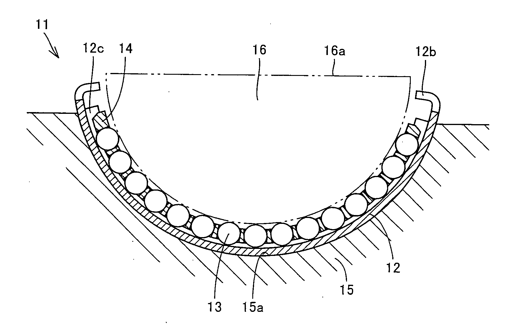
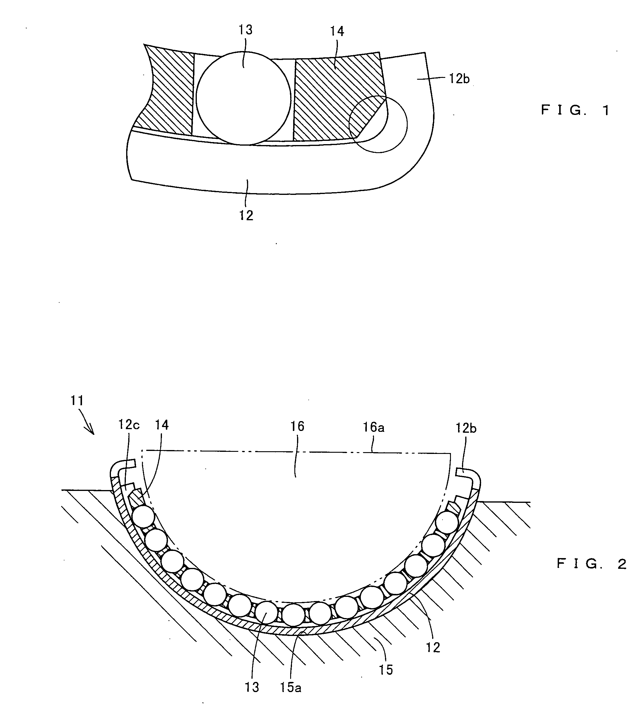
[0051] A cradle bearing 11 according to one embodiment of the present invention will be described with reference to FIG. 2.

[0052] The cradle bearing 11 comprises a circular arcuate outer race 12 arranged in a circular arcuate recessed part 15a provided in a housing 15, a plurality of rollers arranged along the inner circumferential surface of the outer race 12 to support a swash plate 16 swingably, and a retainer 14 for retaining intervals between the plurality of rollers.

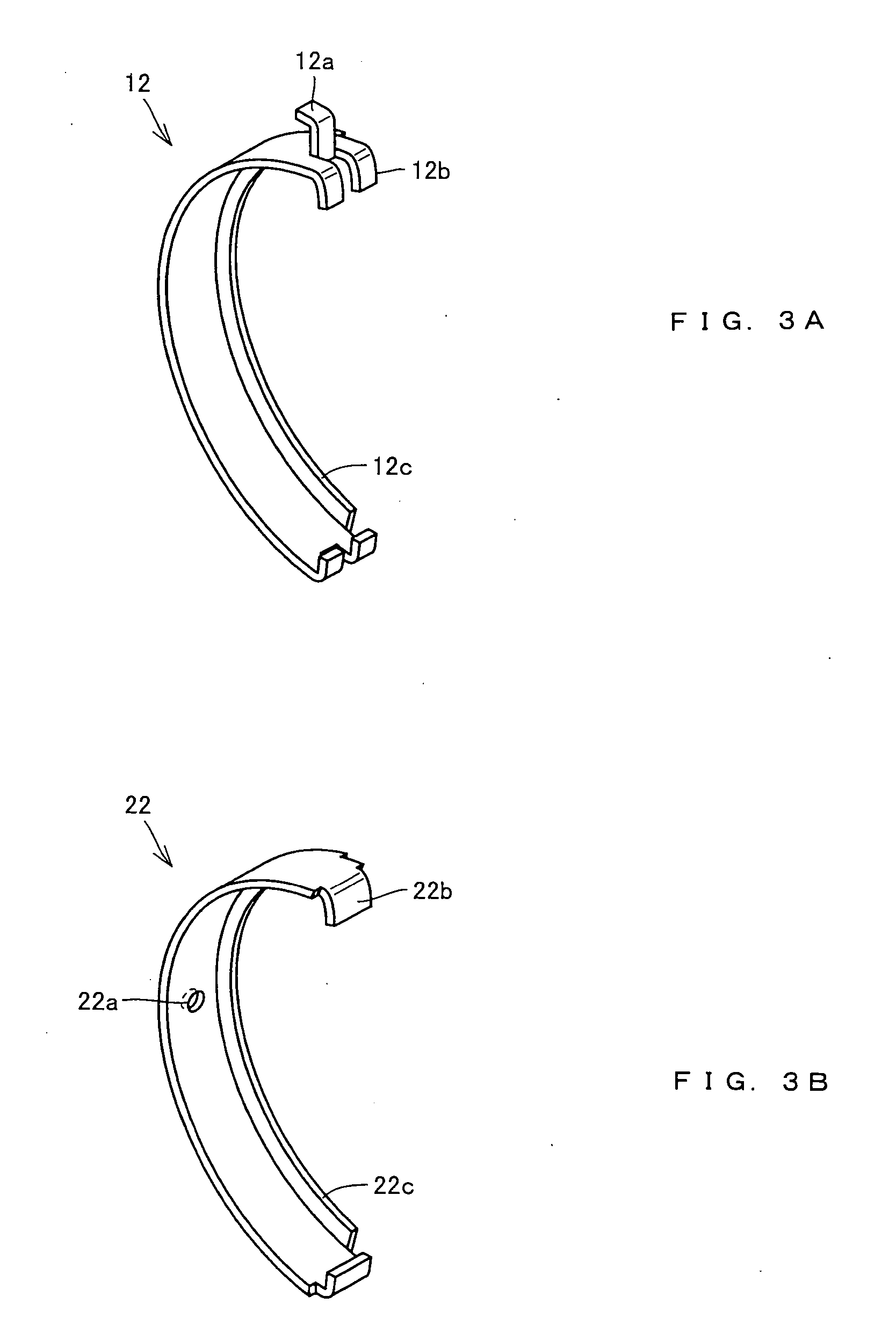
[0053] The outer race 12 is manufactured by pressing a steel plate and in order to be fixed in the circular arcuate recessed part 15a, it comprises a positioning member 12a at its end in the circumferential direction to engage with a positioning hole 15b of the housing 15, and an engagement member 12b for controlling the oscillation amount of the retainer 14 in the circumferential direction as shown in FIG. 3A. In addition, as another meaning for fixing the position of the outer race, a positioning projection 22a...


PUM


Abstract

A cradle bearing comprises a circular arcuate outer race arranged in a circular arcuate recessed part provided in a housing, a plurality of rollers arranged along the inner circumferential surface of the outer race and supporting a swash plate swingably, and a retainer for retaining the interval between the rollers. An engagement member and the end face of the retainer in the circumferential direction are in face-to-face contact with each other.

Description

BACKGROUND OF THE INVENTION [0001] 1. Field of the Invention [0002] The present invention relates to a cradle bearing that supports a swash plate and the like swingably. [0003] 2. Description of the Background Art [0004] Conventionally, a cradle bearing is used as a bearing that supports a swash plate of a swash plate plunger pump as shown in Japanese Unexamined Patent No. 2002-286041. According to the swash plate plunger pump, as shown in FIG. 13, a swash plate 6 is arranged in a circular arcuate recessed part 5a provided in a housing 5 through a cradle bearing 1. [0005] According to this swash plate plunger pump, when the swash plate 6 oscillates, a plunger 7 arranged on a flat surface 6a of the swash plate 6 moves vertically to inhale and feed oil with pressure. In addition, in order to limit the oscillation range of the swash plate 6 within a constant range, the swash plate 6 and the housing 5 are connected through an oscillation amount control member 8. [0006] The cradle bearin...

Claims


Application Information

Patent Timeline
Patent Type & Authority Applications(United States)
IPC IPC(8): F16C33/48F16C19/00
CPCF04B1/2085F16C35/067F16C33/4635F16C19/502F16C2360/00
Inventor KAZAMA, SADATSUNE
Owner NTN CORP
Why Eureka
Try Eureka