Fan and scroll design for high efficiency and low noise

a technology of centrifugal fan and scroll, which is applied in the direction of liquid fuel engine, marine propulsion, vessel construction, etc., can solve the problems of insufficient efficiency and objectionable noise of centrifugal fan assemblies, and achieve the effect of reducing noise output and increasing assembly efficiency

Active Publication Date: 2007-03-08
MAHLE INT GMBH
View PDF7 Cites 4 Cited by
  • Summary
  • Abstract
  • Description
  • Claims
  • Application Information

AI Technical Summary

Benefits of technology

[0007] The present invention provides a centrifugal fan assembly that results in reduced noise output and increased efficiency of the assembly.

Problems solved by technology

Some centrifugal fan assemblies can produce objectionable noise and do not obtain sufficient efficiency.

Method used


Image

  • Fan and scroll design for high efficiency and low noise
  • Fan and scroll design for high efficiency and low noise
  • Fan and scroll design for high efficiency and low noise

Examples


Embodiment Construction

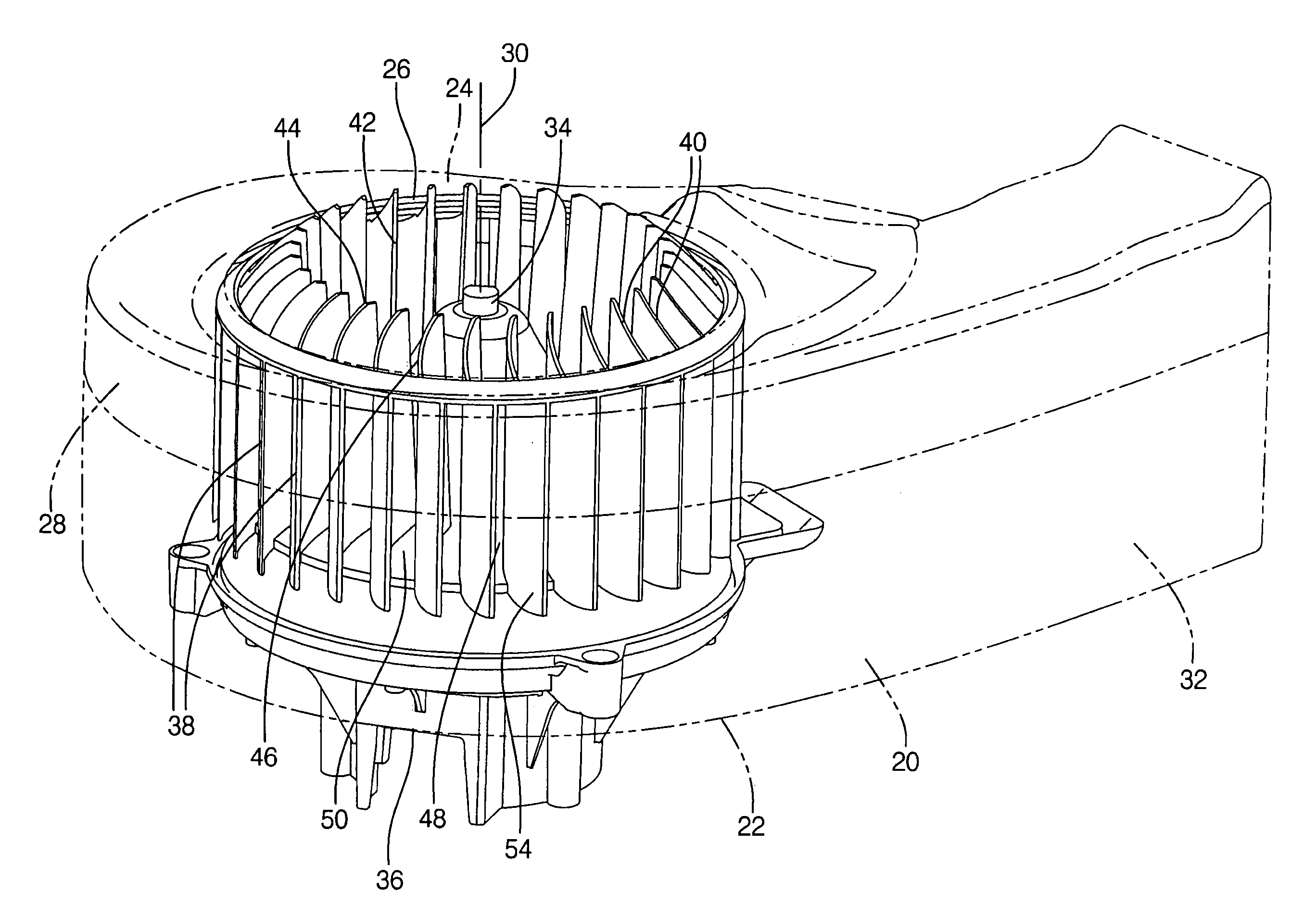
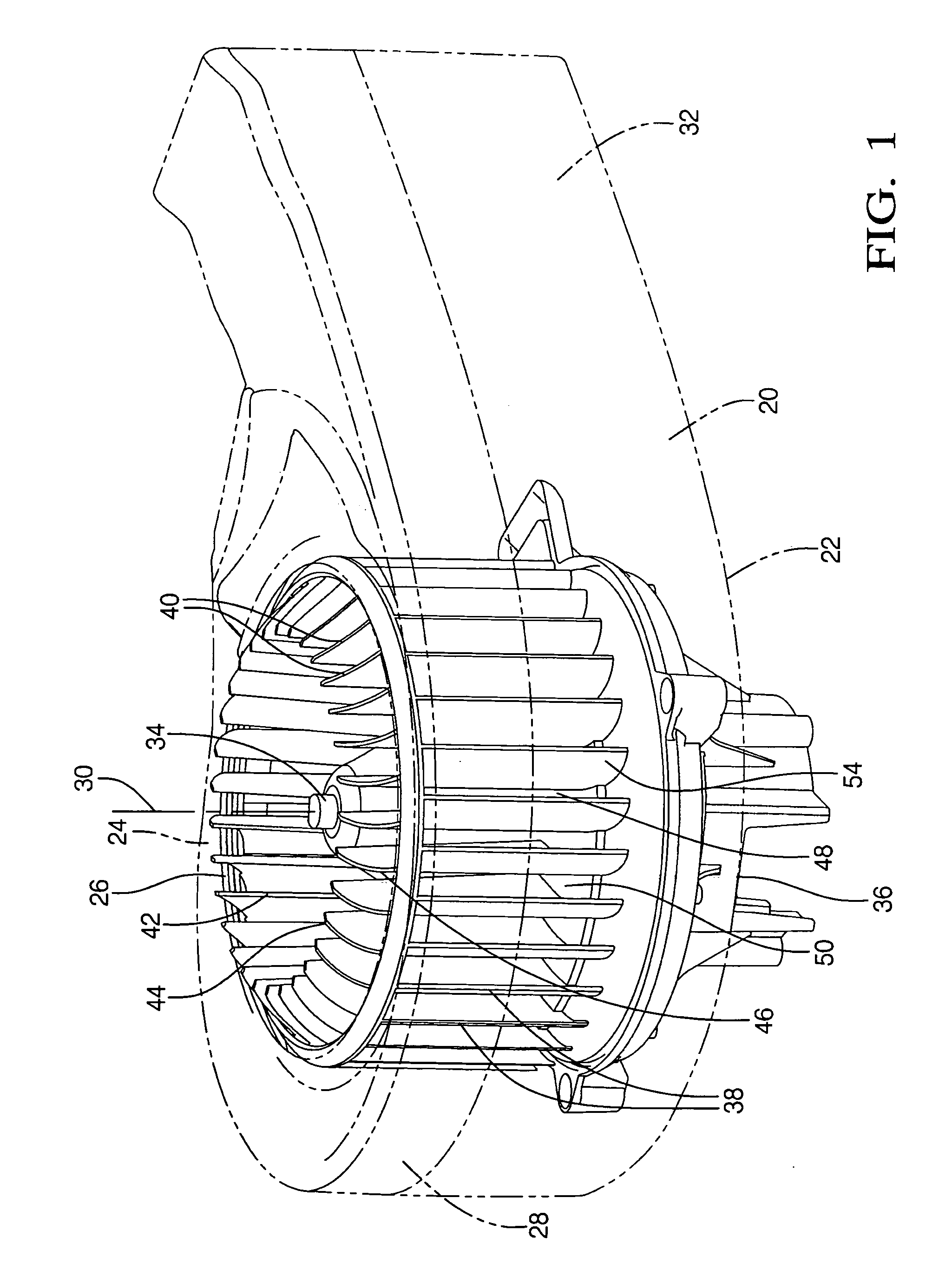
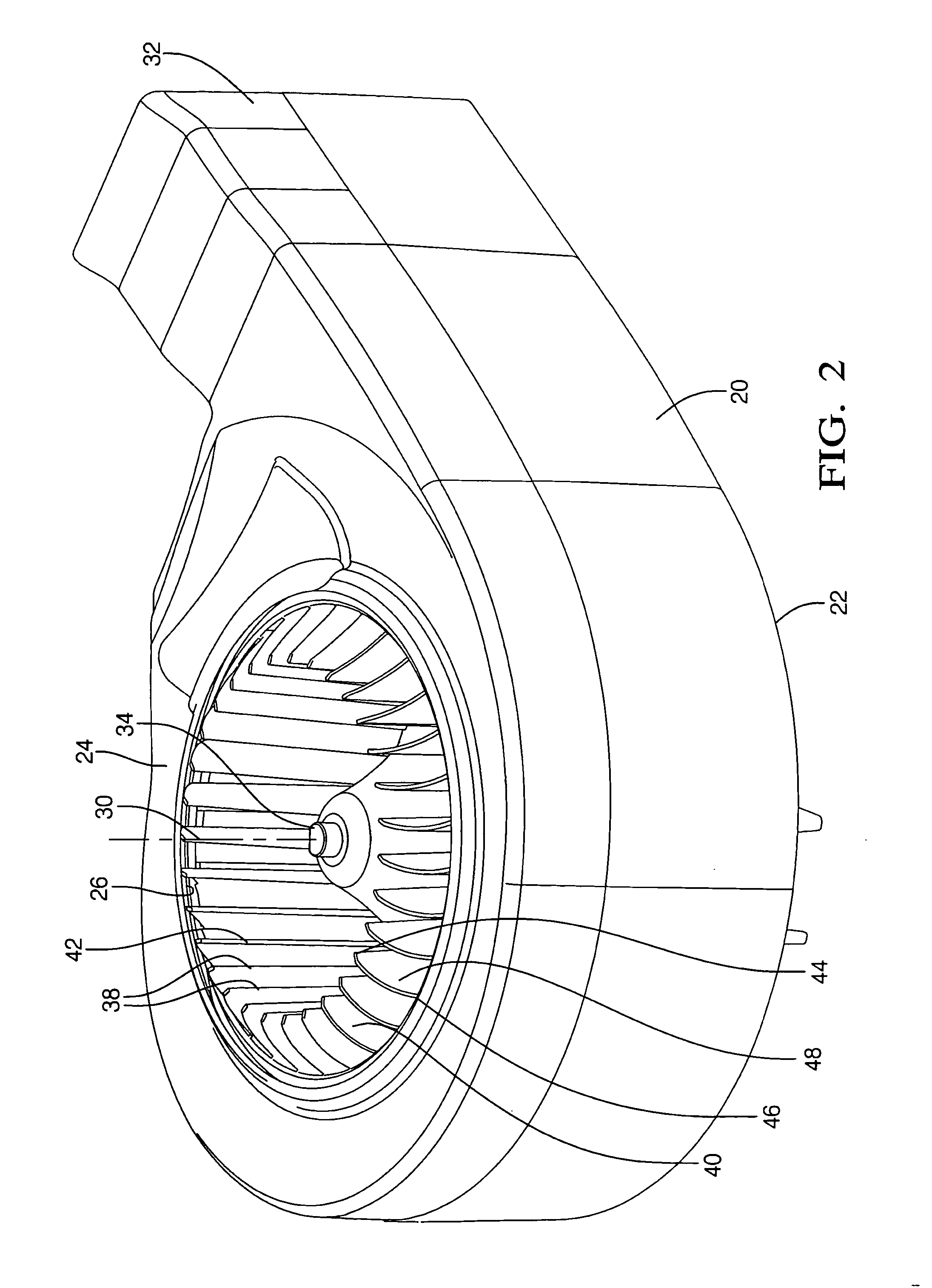
[0017] Referring to the Figures, wherein like numerals indicate corresponding parts throughout the several views, a centrifugal fan assembly is shown.

[0018] The assembly includes a housing 20 having a lower surface 22 and an inlet wall 24 defining an inlet opening 26 that is circular. The housing 20 further defines a scroll wall 28 that spirals about an axis 30 and defines an outlet air passage 32 that extends substantially tangentially to the axis 30. The housing 20 is formed as a diffuser for optimal conversion of kinetic energy to potential energy.

[0019] The assembly also includes a shaft 34 being supported by the housing 20 for rotating about the axis 30 that is aligned with the inlet opening 26. The shaft 34 is configured to allow a motor 36 to rotate the shaft 34.

[0020] A plurality of fan blades 38 are disposed about the shaft 34 and extend radially from the axis 30 for drawing air axially into the fan blades 38 and blowing air radially outwardly into the outlet air passage...


PUM


Abstract

A centrifugal fan assembly including a housing having a lower surface and a parallel inlet wall that defines an inlet opening. A shaft is supported by the housing for rotating about an axis. A plurality of fan blades are disposed about the shaft and extend radially from the axis for drawing air axially into the fan blades and blowing air radially outwardly. The housing defines a scroll wall that spirals about the axis and defines an outlet air passage that extends substantially tangentially to the axis. The fan blades include extensions that extend through the inlet opening and outside of the inlet wall.

Description

BACKGROUND OF THE INVENTION [0001] 1. Field of the Invention [0002] The subject invention relates to centrifugal fan assemblies. [0003] 2. Description of the Prior Art [0004] In the prior art, numerous centrifugal fan assemblies are disclosed for drawing air axially into the center and throwing the air radially. Such centrifugal fan assemblies include a housing having a lower surface and an inlet wall defining an inlet opening and a shaft supported by the housing for rotating about an axis aligned with the inlet opening. A plurality of fan blades are disposed about the shaft and extend radially from the axis for drawing air axially into the blades and for blowing air radially outwardly. The housing defines a scroll wall spiraling about the axis to an outlet air passage that extends substantially tangentially to the axis. An example of a centrifugal fan assembly is shown in U.S. Pat. No. 6,893,220, issued to Eaton et al. [0005] Some centrifugal fan assemblies can produce objectionabl...

Claims


Application Information

Patent Timeline
Patent Type & Authority Applications(United States)
IPC IPC(8): F04D29/44
CPCF04D29/282F04D29/4213F04D29/30
Inventor FARAG, ASHRAFGUZY, STEVEN C.
Owner MAHLE INT GMBH
Why Eureka
Try Eureka