

Sintered sprocket with protrusions
a sprocket and protruding technology, applied in the field of sprockets, can solve the problem that the lateral shift of the chain cannot be accommodated by a clearance, and achieve the effect of preventing the side of the sprocket and the inner plate of the chain from being worn, reducing the wear elongation of the chain, and reducing the risk of lateral shi
- Summary
- Abstract
- Description
- Claims
- Application Information
AI Technical Summary
Benefits of technology
Problems solved by technology
Method used
Image

Examples
first embodiment
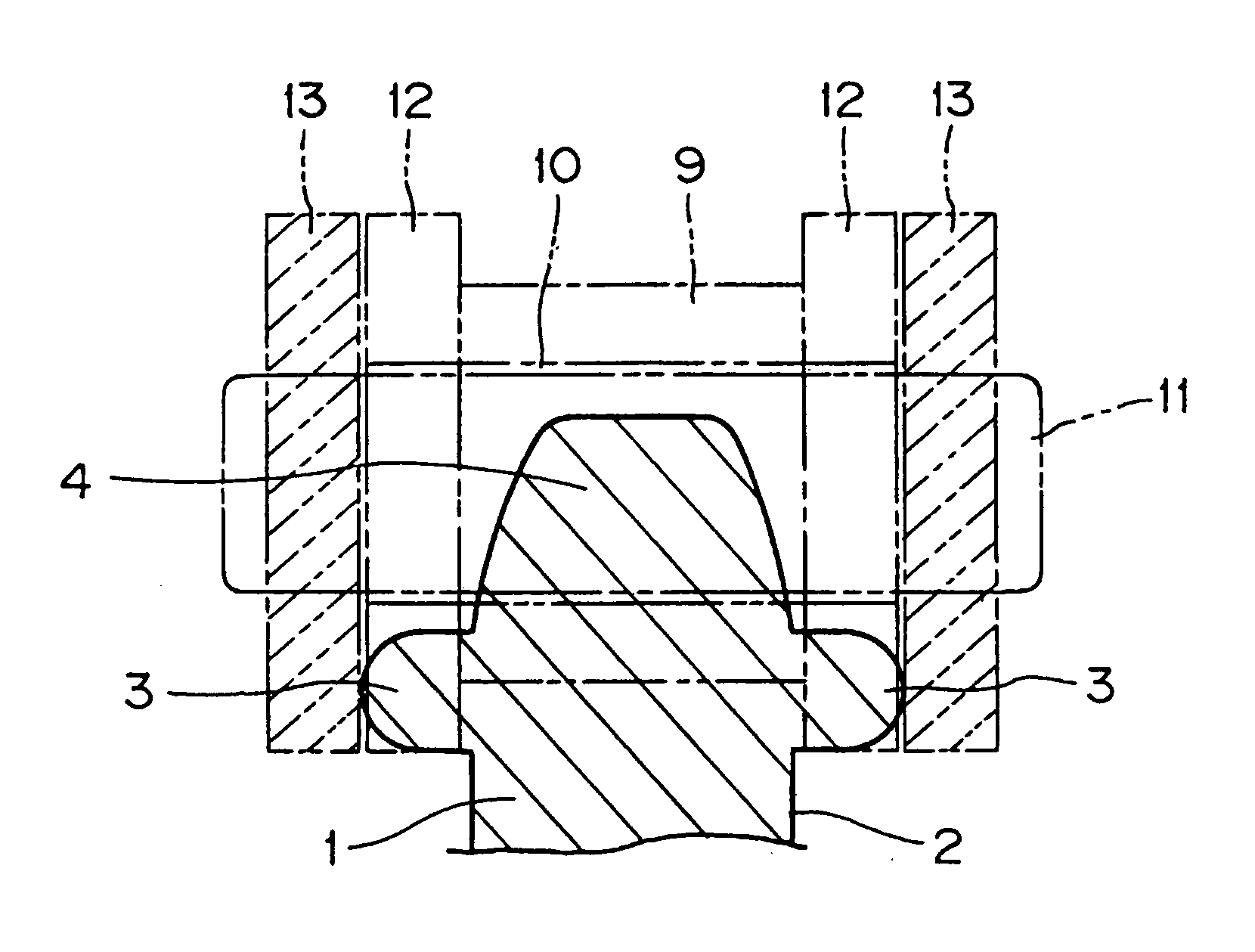
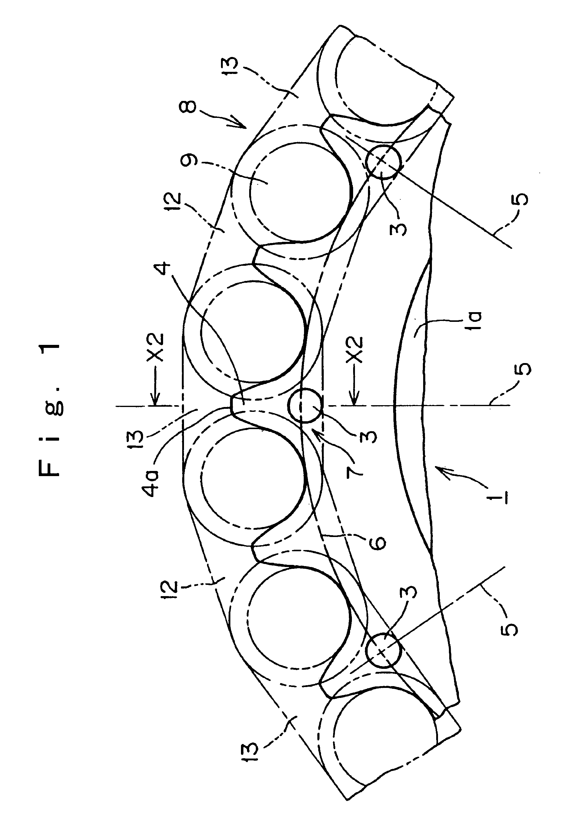
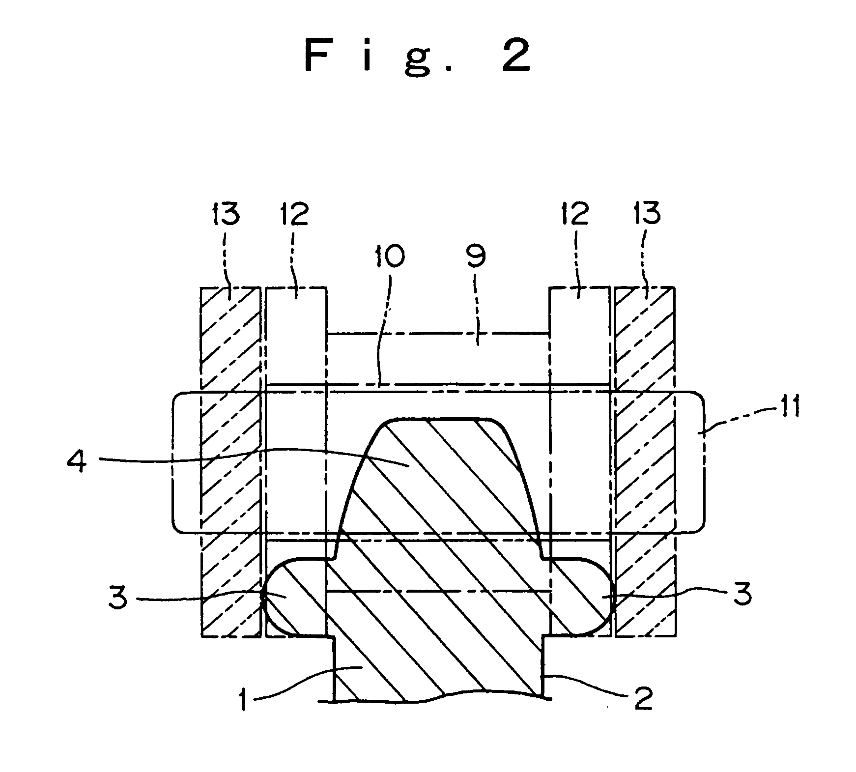
[0018] In the invention, as shown in FIGS. 1 and 2, a sprocket 1 is provided with small protrusions 3 on both of its sides. As shown in FIG. 2, one projection 3 is provided on the right side 2 of the sprocket, and a similar projection 3 is provided on the opposite side. The projections are in the form of cylinders having rounded tips. The length of each protrusion 3 is slightly greater than the thickness of the inner plates 12 of a chain 8 engaged with the sprocket teeth, and the protrusions come into contact with inner faces of outer plates 13 of the chain 8.
[0019] The sprocket 1 is produced by sintering, and the protrusions are preferably unitary with the sprocket body, and composed of the same sintered material of which the hub 1a and the teeth 4 of the sprocket are composed. Alternatively, the protrusions can be separate elements fitted into holes in the sprocket, in which case, the protrusions can be made from any suitable material, and can be made so that they exhibit the same...
second embodiment
[0023] In the invention, as shown in FIGS. 3 and 4, parts that are identical to corresponding parts in the embodiment of FIGS. 1 and 2 are designated by the same reference numbers. Sprocket 15 is provided with small protrusions 16, each of which is substantially in the form of a triangular pyramid having a rounded tip. The pyramid-shaped protrusions 16 are provided on both sides of the sprocket 15.
[0024] As in the first embodiment, the length of each pyramid-shaped protrusion 16 is slightly greater than the thickness of the inner plates 12 of the chain, and the protrusions come into contact with inner faces of the outer plates 13 of the chain. Here, as in the first embodiment, the sprocket is sintered, and the protrusions 16 are preferably unitary with the hub and teeth of the sprocket, and formed from the same sintered material as that of which the hub and teeth of the sprocket are composed. The protrusions 16 are located at the intersections 7 of straight radial lines 5 which conn...
third embodiment
[0025] In the invention, as shown in FIGS. 5 and 6, parts that are identical to corresponding parts in the embodiments of FIGS. 1-4 are designated by the same reference numbers. Sprocket 18 is provided with small protrusions 19, each of which is substantially rectangular in shape. The substantially rectangular-shaped protrusions 19 are provided on both sides of the sprocket 18.
[0026] As in the first and second embodiments, the length of each substantially rectangular-shaped protrusion 19 is slightly greater than the thickness of the inner plates 12 of the chain, and the protrusions come into contact with inner faces of the outer plates 13 of the chain. As in the first and second embodiments, the sprocket is sintered, and the protrusions 19 are preferably unitary with the hub and teeth of the sprocket, and formed from the same sintered material as that of which the hub and teeth of the sprocket are composed. The protrusions 19 are located at the intersections 7 of straight radial lin...
PUM
 Abstract
Description
Claims
Application Information