Chain for use in automobile engine

a technology for automobile engines and chains, applied in driving chains, solid-state diffusion coatings, mechanical devices, etc., can solve the problems shorten the useful life of the chain, and achieve the suppression of abnormal wear elongation, high hardness, and superior wear resistan

Inactive Publication Date: 2008-05-29
TSUBAKIMOTO CHAIN CO
View PDF8 Cites 0 Cited by
  • Summary
  • Abstract
  • Description
  • Claims
  • Application Information

AI Technical Summary

Benefits of technology

[0020]The Cr7C3 layer formed on the base material side of the chromium carbide layer and the outermost Cr23C6 layer have different qualities. The layer principally composed of Cr7C3 exhibits a high degree of hardness, while the layer principally composed of Cr23C6 exhibits superior wear resistance, porosity, heat resistance and lubricity. Even when the chain is used in an extremely deteriorated lubricating oil having a high degree of oxidation, abnormal wear elongation is suppressed, and at the same time excellent wear resistance, heat resistance, and lubricity are achieved.
[0021]Inclusions such as soot or the like in lubricating oil are especially liable to be present in a direct injection gasoline engine or a diesel engine, and can prevent the formation of an oil film on the surface of a pin in a conventional roller chain or bushing chain. In the chain according to the invention, however, the concave recesses formed in the layer on the pins principally composed of Cr23C6 are large enough to receive these inclusion. However, the recesses are preferably only deep enough to receive the inclusions, so that the inclusions do not protrude and interrupt the oil film on the outer surfaces of the pins. As a result, the surface pressure exerted by the pin on the inner surface of the bushing is maintained substantially at a minimum level. At the same time, since the inclusions are not present at the sliding contact surfaces of the pin and the bushing, abrasive wear is suppressed, and wear elongation of the chain due to abrasive wear is decreased. The concave recesses also serve as oil reservoirs, which contribute to superior lubricity in the chain.

Problems solved by technology

When a conventional timing chain is used in highly deteriorated lubricating oil with a high degree of oxidation, it is subjected to the influences of oxidation or corrosion, and can wear excessively due to adhesion between the pins and the bushings, and as a result, the useful life of the chain is shortened.
However, it has been reported that, when such chains are used as timing chains in automobile engines, there have been instances in which the expected endurance is not achieved, and abnormal wear elongation occurs.
However, because heat treatment, and treatment to form the vanadium carbide layer are required, the manufacturing cost of such a chain is high.
When the surface treatment described in Japanese Laid-Open Patent Publication No. 2005-290435 is adapted for use in a roller chain or bushing chain for an automobile engine, the inner surface of the bushings appear to become corroded by highly oxidized lubricating oil, and wear of mutually contacting surfaces of the bushings and the connecting pins is promoted, especially where the surface pressure is high under high mechanical loads.
These inclusions promote abrasive wear, which causes abnormal wear of the mutually sliding surfaces of the pin and the bushing.
The results achieved by this adaptation were no better than those achieved in the case where barrel polishing treatment was applied to a silent chain.
Where the pins and the bushings of a bushing chain or a roller chain are composed of materials having a high affinity for each other, for example in the case where the pins and bushings are composed of the same element, the pins are liable to adhere to the bushings, and the adhesion of the pins to the bushings impairs smooth flexing and sliding of the chain.
Moreover, even if the pins and the bushings are composed of materials having a high affinity for each other, e.g., if the pins and bushings are composed of identical elements, they are not liable to adhere to each other, and wear due to “adhesion” is suppressed, so that smooth flexing and sliding of the chain can take place over a long period of time.

Method used


Image

  • Chain for use in automobile engine
  • Chain for use in automobile engine
  • Chain for use in automobile engine

Examples


Embodiment Construction

[0030]The invention will be described with reference to a roller chain. However, a purpose of the invention is to reduce deterioration of a chain due to the sliding contact between the inner surface of a bushing and the outer surface of a pin, and the principles of the invention are equally applicable to roller chains and to rollerless bushing chains.

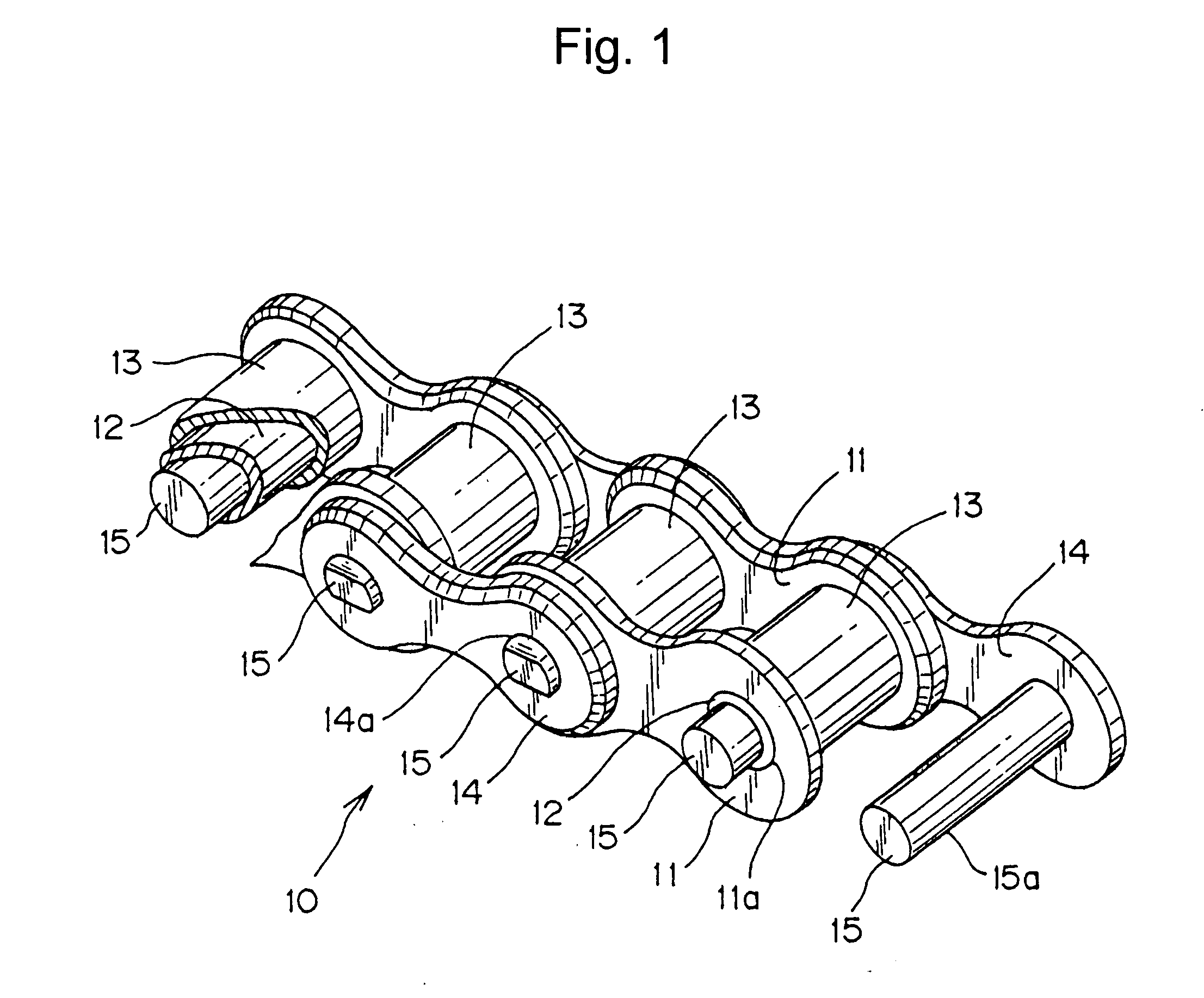
[0031]As shown in FIG. 1, in a roller chain 10, both ends of each bushing 12 are press-fit into bushing holes 11a in a pair of opposite inner plates 11. Pins 15 fit loosely through the bushings, and both ends of each pin 15 are press-fit into pin holes 14a in a pair of outer plates 14 disposed in overlapping relationship with the inner plates on the outer sides thereof. The bushings extend through rollers 13, which are rotatable on the bushings.

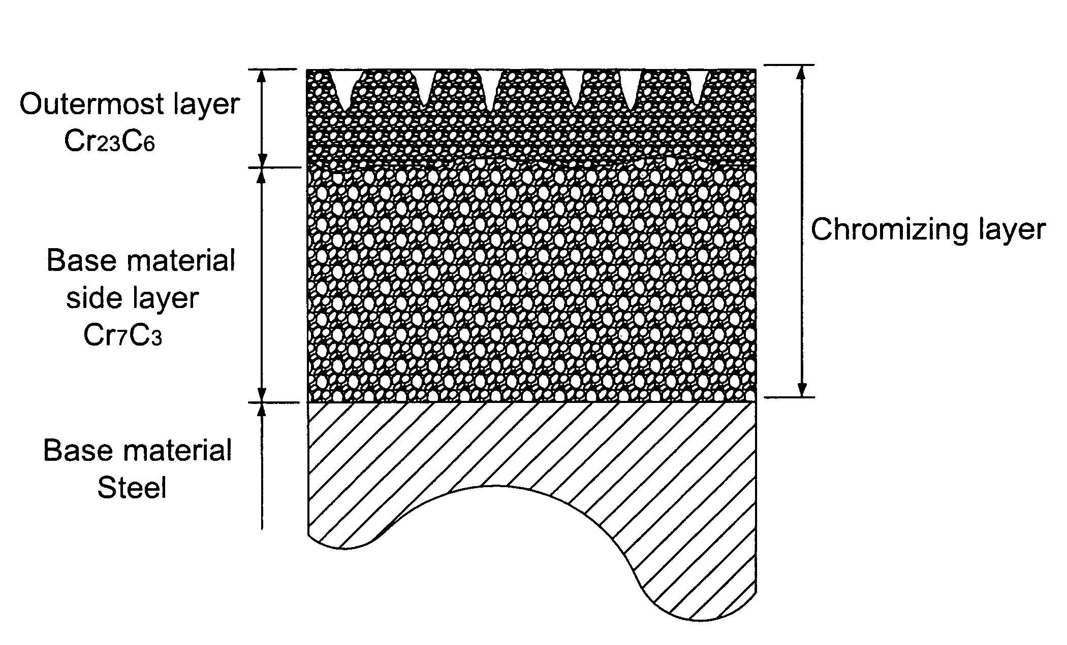
[0032]In the roller chain 10 of the invention, the bushings 12 are composed of alloy steel. The base material of the pins is also steel, and can be a high carbon or low-carbon steel. When the bas...


PUM

PropertyMeasurementUnit
thicknessaaaaaaaaaa
temperatureaaaaaaaaaa
thicknessaaaaaaaaaa

Abstract

The pins of a roller chain or rollerless bushing chain for an automobile engine are subjected to chromizing treatment that forms a two part outer layer having a thick inner section composed primarily of Cr7C3 and a thinner, outermost, layer composed primarily of Cr23C6. The outer layer has convex protrusions and concave recesses. The protrusions are partially removed by barrel polishing to a level such that the depth of each recess is sufficient, but not substantially greater than necessary, for an inclusion received therein to be substantially entirely below the outer surface of the pin, thereby making the surface pressure exerted by portions of the pin on a surrounding bushing substantially as small as possible without exposure of inclusions beyond the outer surface of the pin.

Description

CROSS-REFERENCE TO RELATED APPLICATION[0001]This application claims priority from Japanese patent application 2006-320802, filed Nov. 28, 2006. The disclosure of Japanese patent application 2006-320802 is incorporated by reference.FIELD OF THE INVENTION[0002]This invention relates to a power transmitting chain for use in an automobile engine and a camshaft driving chain, and more specifically it relates to a timing chain for use in an automobile engine.BACKGROUND OF THE INVENTION[0003]Metal roller chains, and rollerless chains known as bushing chains, have come into increasing use as power transmitting media for automobile engines, and have displaced toothed belts and V-belts because of the demand for reliable high speed operation, greater endurance, and increased capacity to withstand mechanical loads, and also because roller chains and bushing chains require less maintenance, and afford greater freedom in the design of the engine layout.[0004]A typical metal chain for use in an au...

Claims


Application Information

Patent Timeline
Patent Type & Authority Applications(United States)
IPC IPC(8): F16G13/06B32B15/00B21L99/00
CPCF16G13/06B21L9/02F16G13/00C23C10/40
Inventor MIYANAGA, SHOTA
Owner TSUBAKIMOTO CHAIN CO
Why Eureka
Try Eureka