Oil-free chain

a technology of oil-free chains and chains, applied in the direction of driving chains, chain elements, gear lubrication/cooling, etc., can solve the problems of increasing the cost of chain production, increasing the overall number of chain parts, and making assembly of chain more difficult, so as to improve the sealing effect, reduce the rate of wear elongation of the chain, and simplify the production of the chain

Inactive Publication Date: 2008-07-03
TSUBAKIMOTO CHAIN CO
View PDF5 Cites 2 Cited by
  • Summary
  • Abstract
  • Description
  • Claims
  • Application Information

AI Technical Summary

Benefits of technology

[0018]Since the bushing shaft supporting bore is preferably formed by a pressing operation that produces an offset in the outer plate, the boss and the bushing support bore are formed simultaneously. No machining operation such as drilling, cutting, milling, or the like, are required to form the bushing support bore, and production of the chain is simplified.
[0019]When oil retaining grooves are formed in the connecting pins, more lubricating oil can be sealed in the spaces between the pins and the bushings. Consequently, sliding wear between the outer circumferential surface of the connecting pins and the inner circumferential surfaces of the bushings can be significantly reduced, and, as a result, the rate of wear elongation of the chain can be significantly reduced.
[0020]By utilizing closely facing rough surfaces of the inner and outer plates to form a labyrinth structure, an improved sealing effect can be achieved so that lubricating oil can be prevented from leaking out, and, at the same time, invasion of dust from the outside can be prevented.
[0021]When the relationship Wj−Wbo>Wbi−Wp is satisfied, even when a tensile force applied to the chain is such that the inner circumferential surface of a bushing and an outer circumferential surface of a connecting pin come into contact with each other, mutual contact between the outer circumferential surface of the protruding end of the bushing and the inner circumferential surface of a bushing supporting bore is prevented. As a result, there is no production of abrasive metal powder from wear due to sliding contact between the outer circumferential surfaces of the protruding ends of the bushings and the inner circumferential surfaces of the bushing supporting bores, and wear elongation of the chain due to the effects of such abrasive metal powder is prevented.
[0022]Where the depth Dj of the bushing supporting bore portion and the protrusion Db of the bushing beyond the outer surface of the inner plate satisfy the relationship Dj<Db, even if the inner link becomes skewed, pivoted or biased with respect to the outer link during operation of the chain, the end surface of the bushing and the bottom surface of a bushing shaft support portion, which have small areas, come into contact with each other, and contact between the outer surface of the inner plate and the inner surface of the outer plate, which have comparatively large areas, is reliably prevented. Thus, smooth bend sliding of the chain for a long period of time can be realized.
[0023]Furthermore, when the relationship Dj+Do<Di+2Db<2Dj+Do is satisfied, even if an inner link becomes skewed, pivoted, or biased with respect to an outer link in a widthwise direction during operation of the chain, the end portion of the bushing does not separate from the bushing supporting bore. Therefore, leakage of lubricating oil and invasion of external dust can be reliably prevented during operation of the chain, sliding wear between the outer circumferential surface of the connecting pin and the inner circumferential surface of the bushing can be reduced over a long period of time. This feature also contributes to the prevention of wear elongation of the chain.

Problems solved by technology

However, need for surface finishing increases the cost of production of the chain.
Since the ring and the elastic seal are additional parts, the overall number of parts in the chain is increased, and assembly of the chain is made more difficult.
The need for these additional parts also increases the cost of production.

Method used


Image

  • Oil-free chain
  • Oil-free chain
  • Oil-free chain

Examples


first embodiment

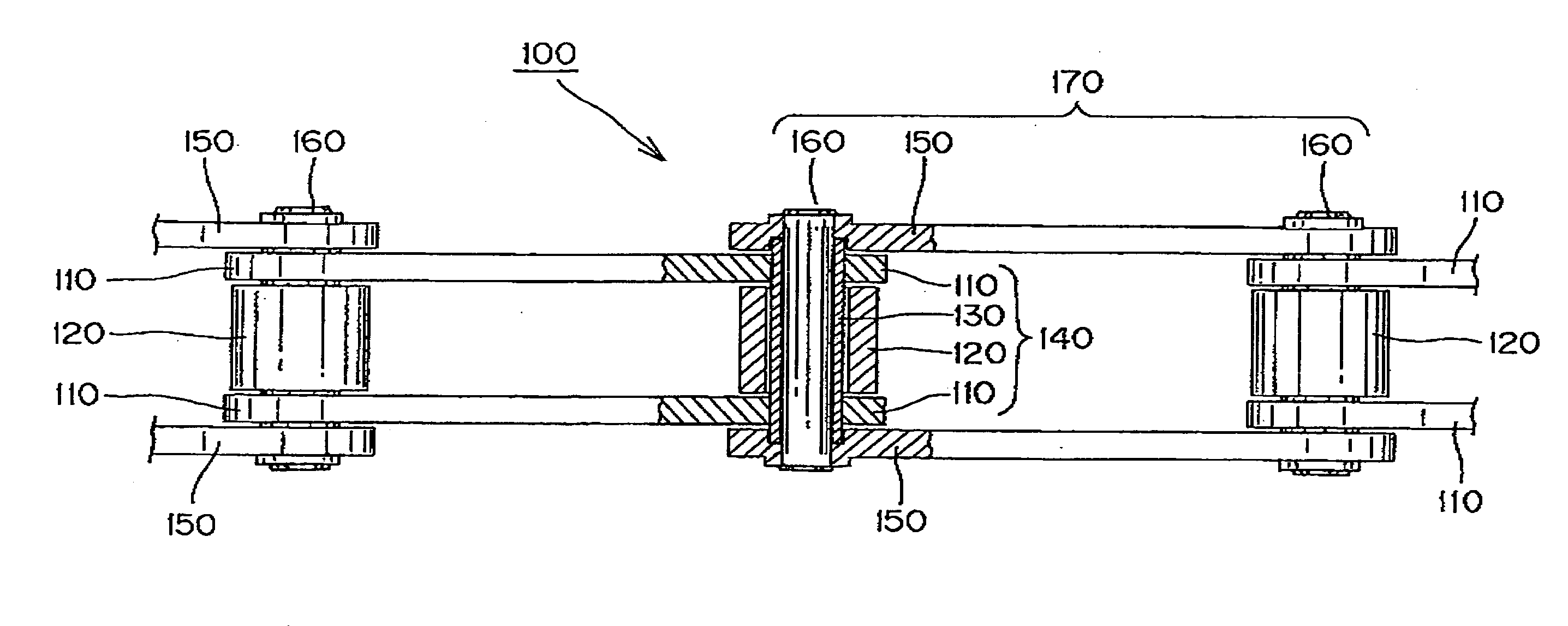
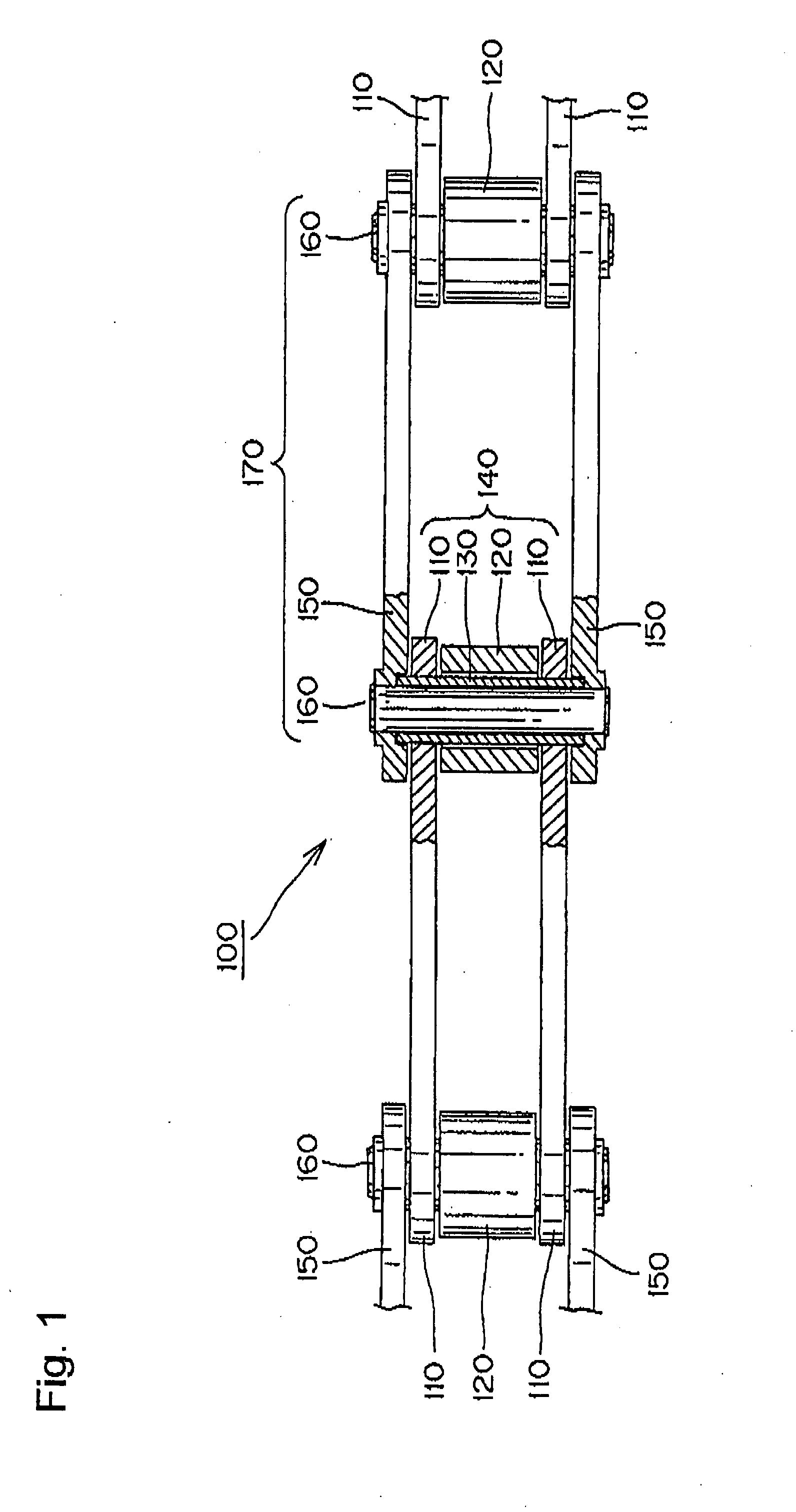
[0034]As shown in FIGS. 1 and 3, a wear resistant and heat resistant, oil-free conveyor chain 100 according to the invention, includes an inner link 140 and outer links 170. In the inner link 140, the ends of a pair of bushings 130, on which rollers 120 fit loosely, are press-fit into holes 111 in a pair of spaced inner plates 110. In the outer links 170, both ends of a pair of connecting pins 160 are press-fit into holes 151 of a pair of spaced outer plates 150.

[0035]The inner and outer links 140 and 170 are connected by virtue of the fact that each connecting pin 160 loosely fits into a bushing 130. Lubricating oil is sealed between the bushing 130 and the connecting pin 160.

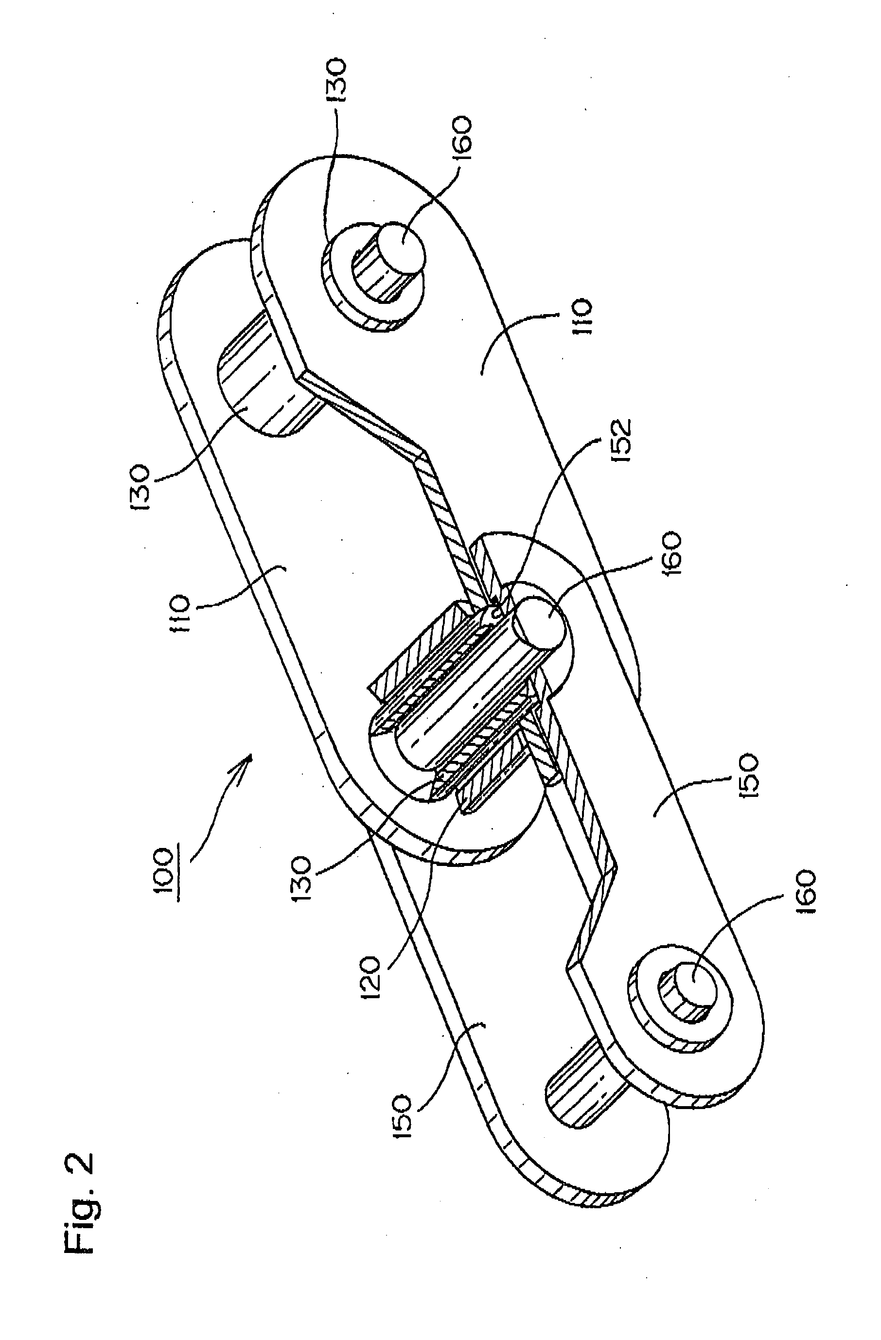
[0036]As shown in FIGS. 2 and 3, bushing supporting bores 152 are formed on the inner sides 153 of the outer plates 150. These bushing supporting bores are open to their full diameter at the inside-facing surfaces of the outer plates. The bushing-supporting bores are formed by pressing the outer plates, thereb...

second embodiment

[0051]In the invention, shown in FIGS. 7 and 8, a wear-resistant and heat-resistant oil-free chain 200 includes an inner link 240 and an outer link 270. In the inner link 240, rollers 220 fit loosely on bushings 230. The ends of each bushing 230 are press-fit into holes 211 of a pair of inner plates 210. In the outer link 270, both ends of a pair of connecting pins 260 are press-fit into holes 251 of a pair of outer plates 250.

[0052]The inner links 240 and the outer links 270 are connected by virtue of the fact that each connecting pin 260 extends through a bushing 230. Lubricating oil is sealed between each bushing 230 and the connecting pin 260 extending through the bushing.

[0053]As shown in FIGS. 7 and 8, the inner surface 253 of an outer plate 250 is provided with a bushing support bore 252 by pressing the outer plate 250, causing a portion thereof to be offset so that, as the bore is formed in the inner side of the plate, a boss is simultaneously formed on the outer side. As a ...


PUM


Abstract

An oil-free chain has bushings which protrude from the outer surfaces of the inner link plates into which they are press-fit, and extend into bushing supporting bores formed in the inner surfaces of the outer link plates of the chain. These bushing supporting bores are formed by a pressing operation which produces offsets in portions of the outer plate, so that, as the bushing supporting bores are formed in the inner surfaces of the outer plates, bosses are simultaneously formed on the outer surfaces. The connecting pins of the chain are press-fit into pin holes in these bosses. The bushing supporting bores are formed without removal of material by machining, and therefore the strength of the outer plates is not compromised.

Description

CROSS-REFERENCE TO RELATED APPLICATION[0001]This application claims priority from Japanese patent application 2006-353488, filed Dec. 27, 2006. The disclosure of Japanese patent application 2006-353488 is incorporated by reference.FIELD OF THE INVENTION[0002]The invention relates to an “oil-free” chain, for use as a power transmitting roller chain, a transfer conveyor chain, or the like. The invention relates more specifically to an oil-free roller chain or rollerless bushing chain, comprising pairs of inner plates and pairs of outer plates in alternating, overlapping relationship along the length of the chain. In such a chain, a pair of bushings for each pair of inner plates are press-fit into bushing holes in the inner plates, and a pair of pins for each pair of outer plates are press-fit in to pin holes in the outer plates. Each pin has an outer surface, and extends through, and fits loosely in, one of the bushings. The term “oil free” does not imply the complete absence of lubri...

Claims


Application Information

Patent Timeline
Patent Type & Authority Applications(United States)
IPC IPC(8): F16G13/02
CPCF16G13/06B65G17/38B65G19/20
Inventor NAKAGAWA, TAKASHIISHIDA, HIROKIAOKI, TOSHIHIKOMIKI, HIROFUMI
Owner TSUBAKIMOTO CHAIN CO
Why Eureka
Try Eureka