Method for displaying a medical implant in an image and a medical imaging system

a technology of medical implants and images, applied in the field of medical implants in images and medical imaging systems, can solve the problems of difficult intuitive acquisition of the relationship between the implant and the tissue being passed through, and the difficulty of the personnel providing the treatment to orient themselves,

Inactive Publication Date: 2007-03-08
SIEMENS HEALTHCARE GMBH
View PDF6 Cites 24 Cited by
  • Summary
  • Abstract
  • Description
  • Claims
  • Application Information

AI Technical Summary

Benefits of technology

[0010] The object is achieved according to the invention by a method with the features of the first independent claim. According to this, provision is made for the medical implant, e.g. a needle, to be displayed in an image of a region to be examined. The region to be examined is represented by a 3D image data record. The coordinates of the implant are correlated with those of the 3D data image record, such that the relative positions of the implant and the region to be examined are also correctly reproduced in the image display. To allow intuitive acquisition, there is provision for the generation of a 2D sectional image of an orthogonal plane and a further 2D sectional image of an implant plane from the 3D image data record. The orthogonal plane is hereby oriented in a perpendicular manner to the insertion direction or the longitudinal direction of the implant. In contrast the implant plane extends in the direction of insertion. The implant plane and the orthogonal plane are therefore perpendicular to each other. The location of the implant is thereby displayed in each instance in the 2D sectional images. The full length of the implant therefore appears in the 2D sectional image of the implant plane, hereafter abbreviated to the “in-plane image”, while in contrast in the 2D sectional image of the orthogonal plane, hereafter abbreviated to the “orthogonal image”, the implant just appears generally as a point or circular object.
[0011] Intuitive acquisition of the position of the implant and in particular its orientation in relation to the region to be examined is hereby achieved in particular due to the two-dimensionality, as experience has proven that orientation is significantly simpler in a two-dimensional plane. Visualizing the implant in two planes oriented orthogonally in relation to each other means that the three-dimensional information about the location of the implant is obtained at the same time and can easily be acquired. Dividing it into two two-dimensional images allows the future path of the implant to be identified. This can be seen in particular from the “in-plane image”. It is thus easy for medical personnel to identify which tissue regions the needle has already penetrated and which tissue regions the needle will encounter next.
[0012] According to one expedient development, the extension or projection of the implant in the longitudinal and therefore the insertion direction is displayed. This additional display allows to doctor to identify immediately which path the needle is taking and which tissue will be penetrated by the needle tip.
[0014] In one expedient development the distance between the orthogonal plane and the needle tip can be varied for displaying in the orthogonal image. In the display of the current needle position the orthogonal plane runs precisely through the needle tip. In other words the needle tip, which is seen as a point or circular shape, shows the precise position. The variable nature of the distance between the orthogonal plane and the needle tip also means that it is possible to project the future path of the needle tip in the orthogonal image. In other words the needle tip is also expediently projected along the insertion direction into the distant plane in the orthogonal image of an orthogonal plane at a distance from the needle tip. This measure also means that medical personnel are able in particular to acquire the future path of the needle tip easily and intuitively.
[0018] To assist further with orientation, a 3D image obtained from the 3D image data record and / or a fluoroscopy image is / are also displayed. A fluoroscopy image in general terms is an image that can be derived directly from the measurement data of the medical imaging device without image reconstruction. When an x-ray computed tomograph is used, this fluoroscopy image corresponds to a regular x-ray image. When displaying the 3D image, it is expedient for the implant plane and / or the orthogonal plane as well as the implant also to be displayed in the 3D image, such that it is also simple for the doctor to acquire the location and position of the needle within the three-dimensional display.

Problems solved by technology

One problem here is displaying the location of the medical implant within the body in such a manner for medical personnel that the actual position, in particular the relative position of the implant in relation to the individual organs, can be acquired as intuitively as possible by the personnel providing the treatment.
With such a visualization of the implant in a three-dimensional image, it is however often difficult for the personnel providing the treatment to orient themselves, due to the complexity of the individual organs.
It is particularly difficult for medical personal to identify how the implant will progress further.
However intuitive acquisition of the relationship between the implant and the tissue being passed through is difficult here too.

Method used


Image

  • Method for displaying a medical implant in an image and a medical imaging system
  • Method for displaying a medical implant in an image and a medical imaging system
  • Method for displaying a medical implant in an image and a medical imaging system

Examples


Embodiment Construction

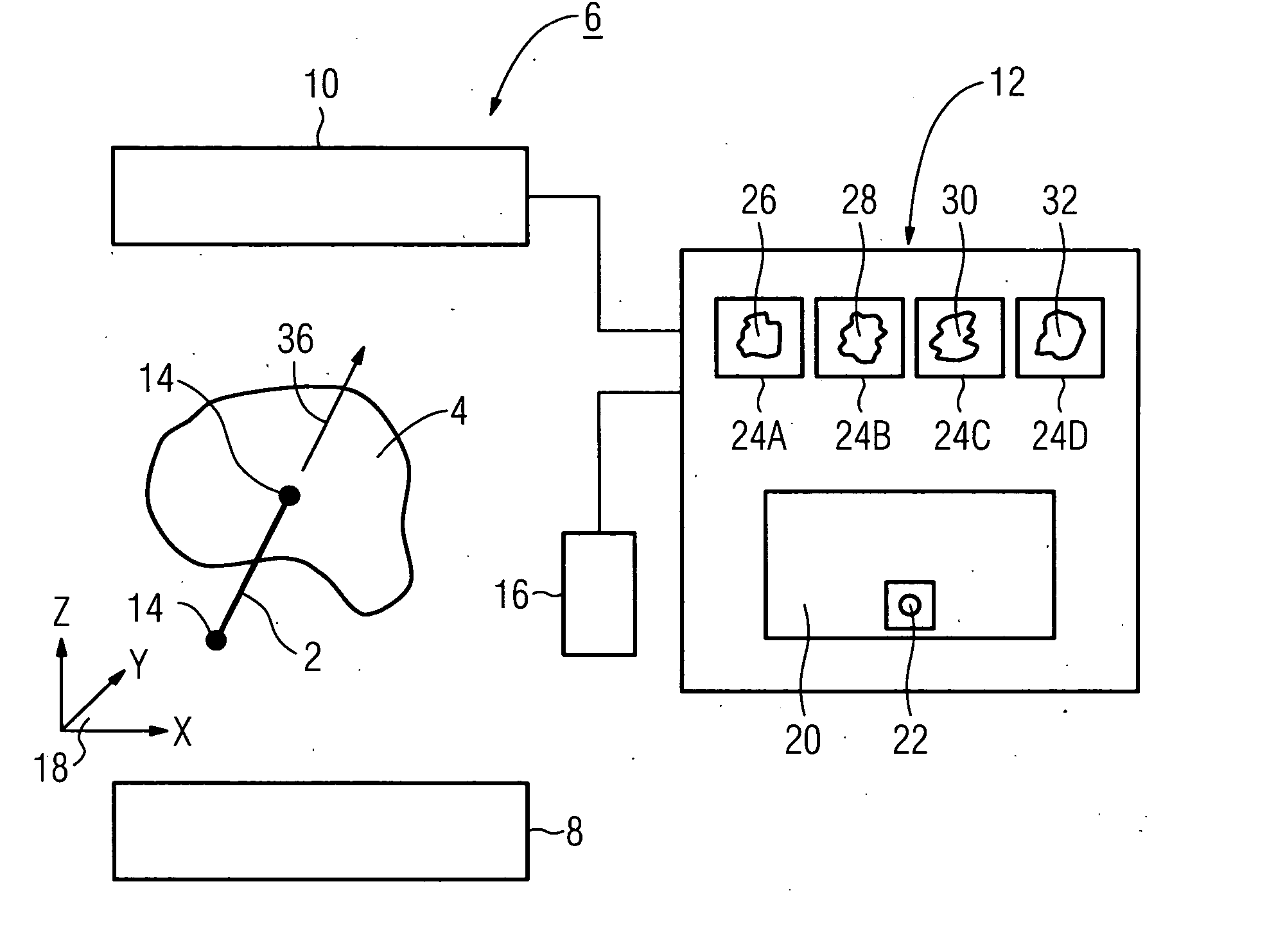
[0032] The medical imaging system shown in a highly simplified manner in FIG. 1 is used to assist during the medical treatment of a patient. It is used in particular to visualize the position of a treatment device, in particular a needle 2, in relation to a region 4 to be examined, in a manner that can be acquired intuitively by medical personnel. In the exemplary embodiment the medical imaging system comprises a medical imaging examination device 6, for example a C-arm computed tomography device, a magnetic resonance device or even an angiography system. The examination device 6 has a radiation source 8 and a detector 10. The radiation source 8 is in particular an x-ray radiation source and the detector 10 is an x-ray detector. The radiation source 8 and detector 10 are disposed opposite each other. The patient with the region 4 to be examined is located between them. The measurement data acquired by the detector 10 is transmitted as raw image data to an image-processing system 12....


PUM


Abstract

To allow safe treatment of a patient, in particular a puncture or biopsy using a needle, a 2D sectional image of an implant plane and a further 2D sectional image of an orthogonal plane are generated from a 3D image data record of a region to be examined. The two planes are hereby oriented such that the needle is on the one hand located within the implant plane and on the other hand is oriented in a perpendicular manner in respect of the orthogonal plane. The in particular parallel display of the 2D images allows the doctor to acquire the relative position of the needle in relation to the region to be examined in a simple and intuitive manner.

Description

CROSS REFERENCE TO RELATED APPLICATIONS [0001] This application claims priority of German application No. 10 2005 041 602.0 filed Sep. 1, 2005, which is incorporated by reference herein in its entirety. FIELD OF THE INVENTION [0002] The invention relates to a method for displaying a medical implant extending in the direction of insertion, in particular a treatment device, e.g. a needle, in a medical image of a region to be examined. The invention further relates to a medical imaging system for implementing said method. BACKGROUND OF THE INVENTION [0003] During the medical treatment of a patient, for example during the treatment of tumors, aneurysms and stenoses, a medical treatment device, for example a needle, is inserted into the body and guided to the diseased point in the body. This is then treated for example by puncture or biopsy. In the case of certain organs, for example the spleen, gallbladder, bowel or spinal cord, the medical treatment device, referred to here generally a...

Claims


Application Information

Patent Timeline
Patent Type & Authority Applications(United States)
IPC IPC(8): A61B5/05
CPCA61B5/416A61B6/504A61B19/201A61B5/06A61B19/5244A61B2019/507A61B2019/5238A61B19/52A61B34/20A61B90/11A61B90/36A61B2034/107A61B2090/376
Inventor DEINZER, FRANKBRUNNER, THOMASPFLAUM, MICHAEL
Owner SIEMENS HEALTHCARE GMBH
Why Eureka
Try Eureka