
Sign Assemblage

Inactive Publication Date: 2007-03-15
KINGS SYST HONG KONG
View PDF7 Cites 1 Cited by
  • Summary
  • Abstract
  • Description
  • Claims
  • Application Information

AI Technical Summary

Benefits of technology

[0010] There are many advantages to the present invention. The neck portion of the fastening member at the back of the sign allows slight angular motions of the sign such that it can be pried from the frame for ease of replacement. In the most preferred embodiment, the ridge or ridges run along the interior area of the sign, acting as the center of rotation for the sign to rotate during the removal process. Yet the neck portion also allows the clamps to tightly secure the sign to the wall frame. In another embodiment, one or more ridges are provided along the interior surface of the back of the strip, keeping the edges of the strip approximately the same thickness as the interior.
[0011] In the preferred embodiment, the two clamps are arranged to grip the sign from the two sides of the ridge that is parallel to the longitudinal edge of the sign such that the rotational movement of the sign as it is detached from the frame results in a force having the same direction as the clamping force of the clamps, thereby reducing the clamping force and making the removal process easier without causing damage to the clamps.
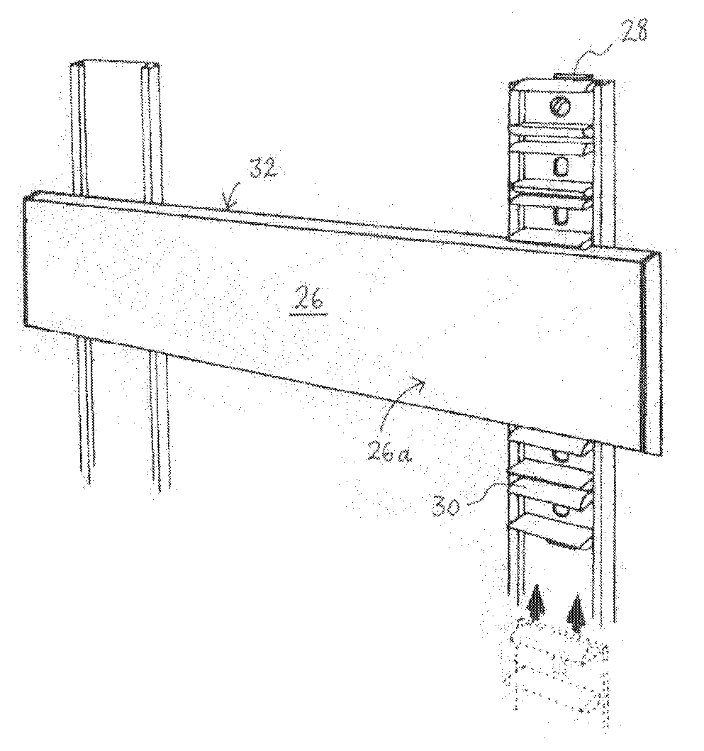
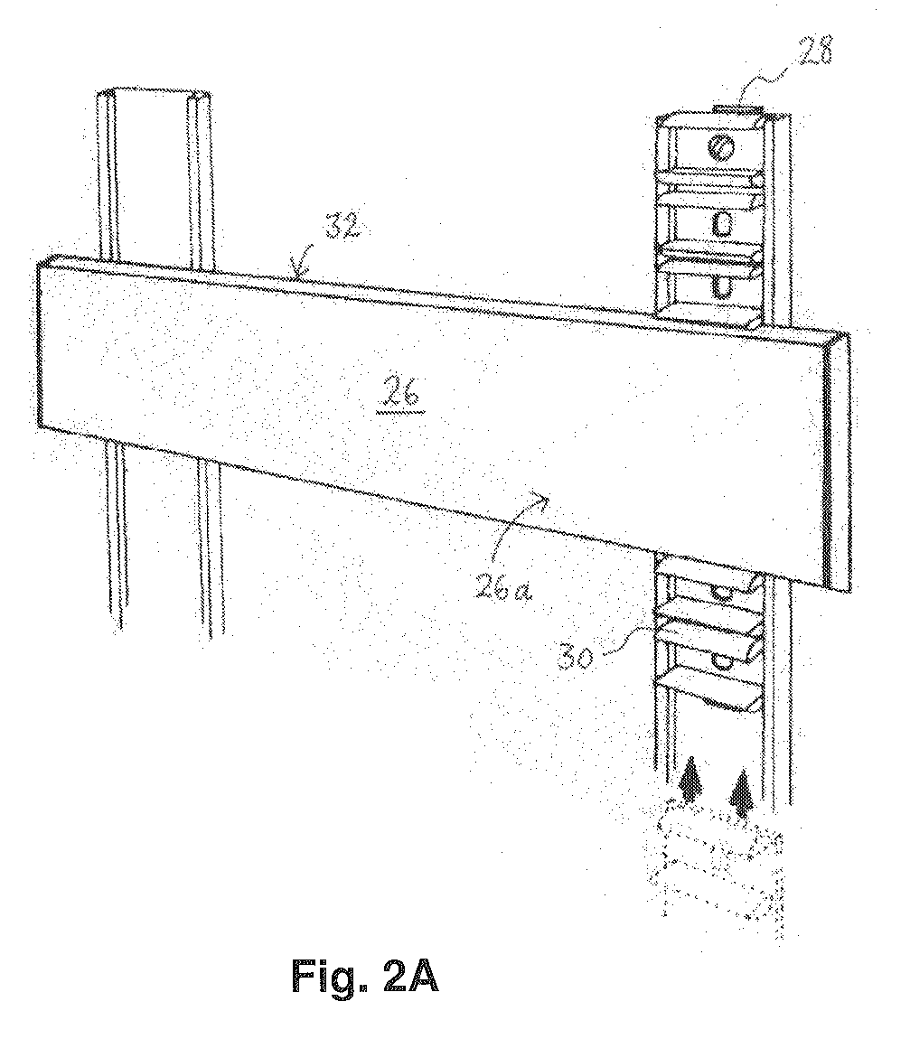
[0012] Another advantage of the present invention is that the ridges are preferably provided within the interior areas of the sign such that there are no flanges along the edge of the sign as found in the prior art assembly shown in FIGS. 2A and 2B. As a result, the gap between the strips may be substantially narrowed because more space is needed for the rotation of the prior art strip with a wide flange to clear away from an adjacent strip by rotational movement. The possibility of aligning the strips one next to another in a compact manner according to the present invention with virtually invisible gaps therebetween improves the aesthetic appearance of the sign assembly.

Problems solved by technology

In some prior art methods the sign strips are difficult to mount and demount, while in other prior art methods, the signs are too readily pried off.

Method used


Image

  • Sign Assemblage
  • Sign Assemblage
  • Sign Assemblage

Examples


Embodiment Construction

[0023] Referring first to FIG. 3, a frame according to the present invention is provided with top and bottom metal strips 35a, left and right side metal strips 35b and mounting holes 36. The left and right side metal strips 35b contain a supporting border 38 and two tracks 40 running parallel to the longitudinal axis (shown as dotted line 42) of the metal strip. In this embodiment, the two tracks 40 define a longitudinal space 41 therebetween with the inner edges of the tracks 40a provided with a beveled shape. In FIG. 3, four clamping units 45 are shown attached to the frame with two on either side of the frame. In this embodiment, the clamping units are fixed onto the frame by sliding the base of each unit (see FIGS. 5A and 5B) into the space 41 between the tracks 40.

[0024] Turning now to FIG. 4A to 4C, a sign strip 43 according to the present invention is provided with a front illustration surface 44 on which the content of the sign, such as the name of the company, can be fixed...


PUM


Abstract

A sign system with a frame and at least one sign. The sign has at least one protruding ridge extending from the backside with the ridge having a narrow neck portion proximate the backside. At least one clamping unit is fixed to the frame with at least one pair of clamps to securely the neck portion of the ridge such that the frame is reversibly but securely fastened to the frame.

Description

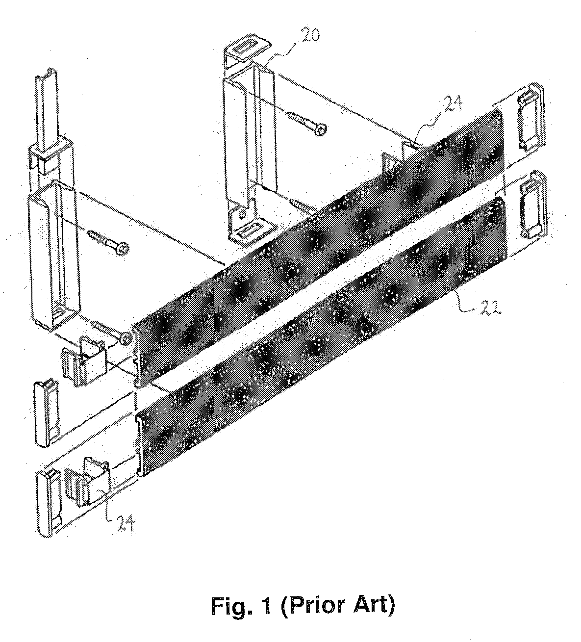
FIELD OF INVENTION [0001] This invention relates to a sign system, and in particular an easily removable sign system for ease of replacement and handling. BACKGROUND OF INVENTION [0002] Signs, in particularly signs that are used in buildings with multiple tenants, are known to have a frame with replaceable sign strips for ease of replacement. For example, FIG. 1 shows a prior art wall-mounted sign system that has a pair of wall mounted columns 20 adapted to allow the directory panel or sign strips 22 to be clamped thereon via brackets 24 attached to the back of the strips. The sign strips in this example have to be removed from the top one by one, such that if a strip from the bottom of the stack of strips needs to be changed, all the strips have to be removed by sliding upwards from columns 20. [0003] In another prior art example as shown in FIGS. 2A and 2B, The sign strips 26 are mounted onto the wall-mounted column 28 via clips 30 that have a cross-section shape generally of a se...

Claims


Application Information

Patent Timeline
IPC IPC(8): G09F7/00
CPCG09F7/08
Inventor CHEUNG, KIN NGAM
Owner KINGS SYST HONG KONG
Learn More