

Pipette verification device and pipette
a verification device and pipette technology, applied in the field of liquid dispensing systems, can solve the problems of inability to verify the performance of pipette, and inability to carry out tests with instruments
- Summary
- Abstract
- Description
- Claims
- Application Information
AI Technical Summary
Benefits of technology
Problems solved by technology
Method used
Image

Examples
Embodiment Construction
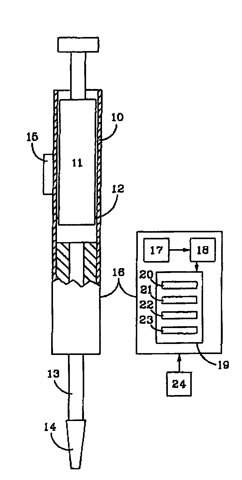
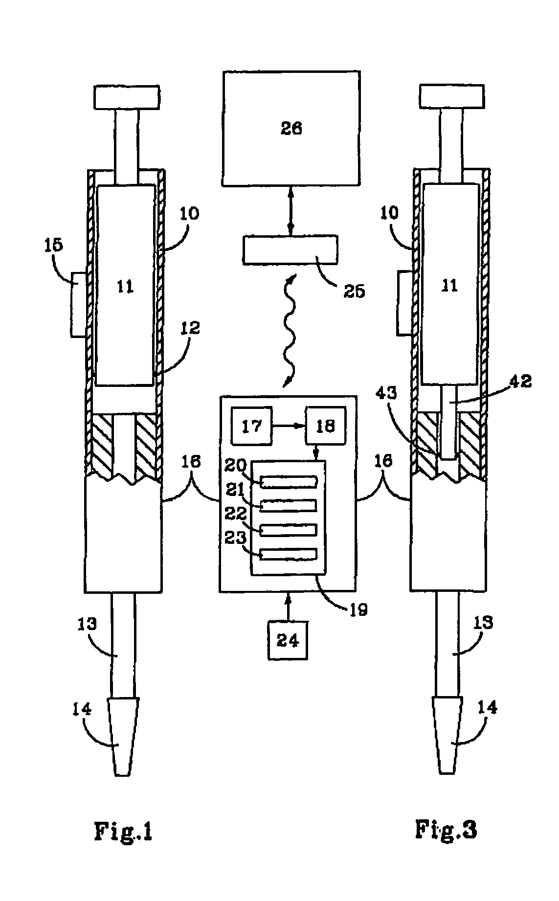
[0032] The pipette shown in FIG. 1 includes, in a conventional manner, a cylindrical chamber 10 into which a manually actuated piston 11 can slide. A seal 12 seals the contact between cylinder 10 and piston 11. Cylinder 10 is extended, at its base, by a shaft 13, whose end is provided with a removable conical dispensing tip 14. Finally, a counter 15 allows the operator to determine the volume of liquid to be dispensed. The travel of piston 11 will thus be automatically determined to follow this instruction.
[0033] Piston 11 can also be actuated by a motor, which replaces the action exerted manually by the operator.
[0034] The peculiarity of this pipette lies in the fact that it is provided with a verification module 16, which, in the example shown, occupies the extension of cylinder 10 and includes: [0035] a sensor 17 for supplying an air or any other fluid pressure measurement at two points of shaft 13 and a measurement of its temperature; [0036] a microprocessor 18 supplying, from...
PUM
 Abstract
Description
Claims
Application Information