Solar energy collection system for outdoor umbrella

a solar energy collection and outdoor umbrella technology, applied in the field of outdoor umbrellas, can solve the problems of not working properly, battery units needing to be recharged or even replaced regularly, and activity with outdoor umbrellas may be forced to cancel

Inactive Publication Date: 2007-03-15
LI WANDA YING
View PDF9 Cites 29 Cited by
  • Summary
  • Abstract
  • Description
  • Claims
  • Application Information

AI Technical Summary

Benefits of technology

[0009] A main object of the present invention is to provide an outdoor umbrella comprising a solar energy collection system whic

Problems solved by technology

For the first power system, the main problem is that the battery unit needed to be recharged or even replaced regularly in order to provide continuous supply of adequate electricity for the illumination system.
If the user forgets to recharge or replace the battery unit, the illumination system will not function properly and the activity with the outdoor umbrella may be forced to cancel.
The problem in association with this type of solar energy collection system is that the solar energy collection panel is usually permanently mounted on the main supporting frame in such a manner that the solar energy collection panel is both not adjustable and not detachable.
As a result, the solar energy collection system may not be capable of adsorbing or collecting solar energy in an efficient manner so that it may not collect adequate solar energy for operating the illumination system for a desirable period of time.
Moreover, since virtually all of the solar energy collection panels mounted on the outdoor umbrella, there is nothing a user can do in repairing or cleaning the solar energy collection panel when it becomes dirt

Method used


Image

  • Solar energy collection system for outdoor umbrella
  • Solar energy collection system for outdoor umbrella
  • Solar energy collection system for outdoor umbrella

Examples


Embodiment Construction

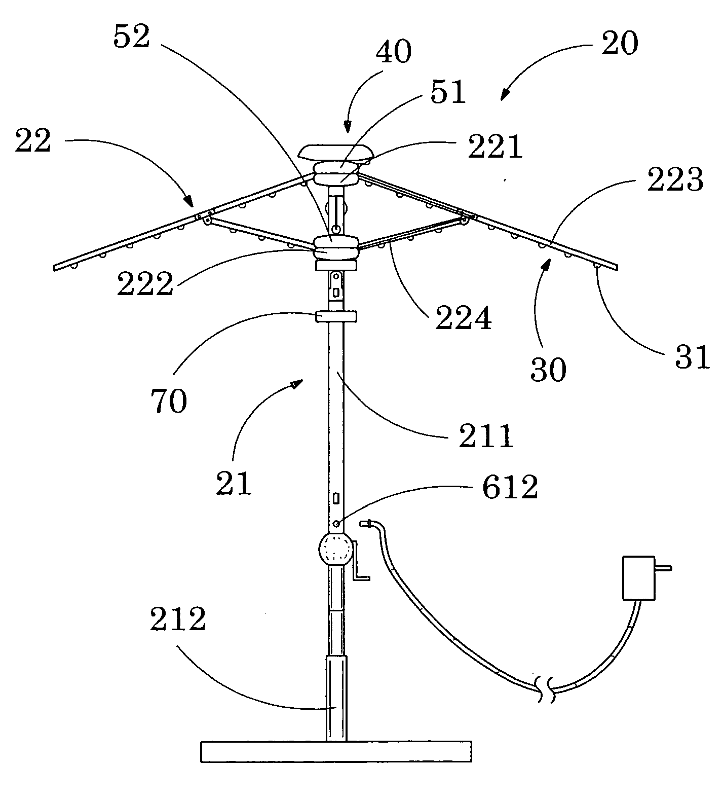
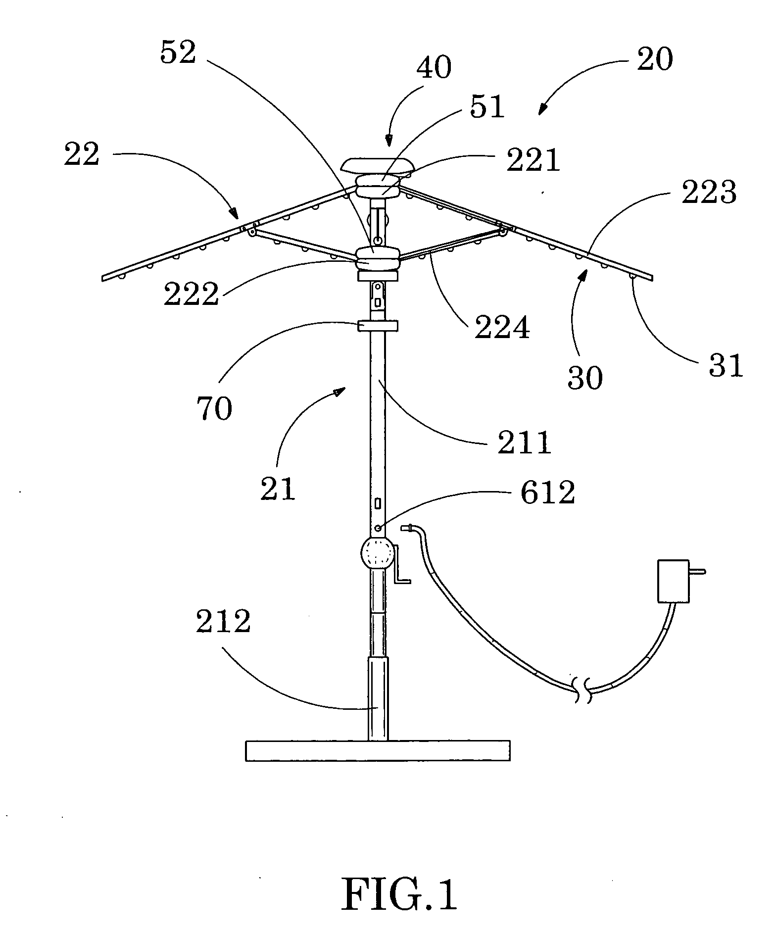
[0034] Referring to FIG. 1, FIG. 6A, FIG. 6B and FIG. 7A to FIG. 7D of the drawings, an outdoor umbrella according to a preferred embodiment of the present invention is illustrated. According to the preferred embodiment of the present invention, the outdoor umbrella comprises an awning 10, an umbrella frame 20, an illumination system 30, and a solar energy collection system 40.

[0035] The umbrella frame 20 comprises an upward supporting post 21, and an awning supporting frame 22 radially extended from a top portion of the supporting post 21 to support the awning 10 to define a shading area thereunder.

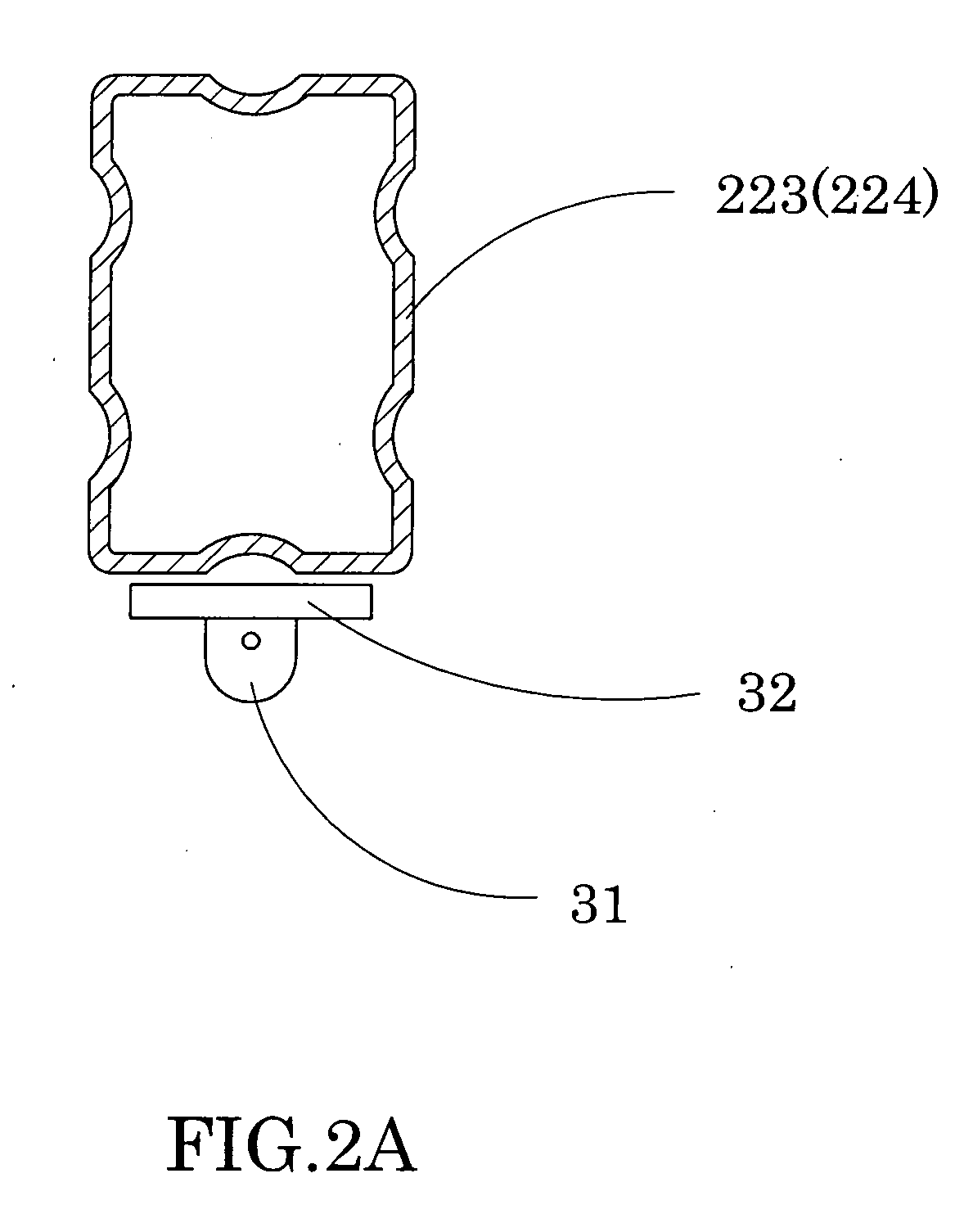
[0036] The illumination system 30 is provided on the umbrella frame 20 for illuminating the shading area of the awning 10. On the other hand, the solar energy collection system 40 comprises a supporting adjustor 41 and a solar energy collector 42.

[0037] The supporting adjustor 41 has an upper pivot portion 411 and a lower retention portion 412 detachably mounted on the top portion of ...


PUM


Abstract

An outdoor umbrella includes an awning, an umbrella frame, an illumination system, and a solar energy collection system. The solar energy collection system includes a supporting adjustor and a solar energy collector. The supporting adjustor has an upper pivot portion, and a lower retention portion detachably mounted on the top portion of the supporting post. The solar energy collector, which is electrically connected with the illumination system, is pivotally mounted on the pivot portion of the supporting adjustor at a position above the awning, wherein the solar energy collector is adapted to selectively adjust a tilt angle with respect to the supporting post for directly facing towards sunlight to maximize solar energy collection so as to supply electrical power to the illumination system.

Description

BACKGROUND OF THE PRESENT INVENTION [0001] 1. Field of Invention [0002] The present invention relates to an outdoor umbrella, and more particularly to a detachable solar energy collection system for an outdoor umbrella, wherein the solar energy collection system is adjustable for collecting solar energy at an optimal tilt angle. [0003] 2. Description of Related Arts [0004] A conventional outdoor umbrella usually comprises an awning, a main supporting frame comprising an awning frame and a central post frame, and an illumination system supported on the main supporting frame for providing illumination towards an underneath of the awning. In order to provide electricity to the illumination system, the outdoor umbrella further comprises a power system mounted on the main supporting frame to electrically connect with the illumination system. The power system may be embodied as one of the followings: first, the power system may comprise a battery unit (which is usually rechargeable) mount...

Claims


Application Information

Patent Timeline
IPC IPC(8): E04H15/10
CPCA45B3/04A45B2200/1027F21S9/035F21V33/006H02S20/00Y02E10/47Y02E10/50A45B3/00F24J2/523F24S25/10H02S10/40Y02B20/72
Inventor LI, WANDA YING
Owner LI WANDA YING
Why Eureka
Try Eureka