Flow control system

a flow control and flow rate technology, applied in the direction of fluid pressure control, process and machine control, instruments, etc., can solve the problems of affecting the flow rate of the fluid supplied from the supply line, the flow control system is liable to change, and the flow rate of the fluid is liable to become difficult or take more time, so as to achieve high precision the effect of stabilizing the flow ra

Inactive Publication Date: 2007-03-15
ADVANCE DENKI KOUGYOU
View PDF28 Cites 18 Cited by
  • Summary
  • Abstract
  • Description
  • Claims
  • Application Information

AI Technical Summary

Benefits of technology

[0007] An object of the present invention is to provide a flow control system enabling high precision stabilization of the flow rate of a fluid even in cases where pressure fluctuations of the outlet fluid of the flow control system occur.
[0009] According to this, the influence of pressure fluctuation of the inlet (fluid supply part side) fluid can be suppressed by the first pressure control valve part, while the influence of pressure fluctuation of the outlet (fluid usage part side) fluid can be suppressed by the second pressure control valve part. Thus, high precision stabilization of the flow rate of the fluid supplied from the supply line to the fluid usage part is possible not only in cases where pressure fluctuation of the inlet (fluid supply part side) fluid of the flow control system occurs, but even in cases where pressure fluctuation of the outlet (fluid usage part side) fluid occurs. This is due to the fact that the differential pressure before and after the pressure loss part is maintained at a predetermined value by the first pressure control mechanism and the second pressure control mechanism.
[0011] According to this, it is possible to stabilize at a high precision the flow rate of fluid running in each of the supply lines. In addition, particularly, during mixing of fluids, even if changing the flow rate of fluid in some of the supply lines, it is possible to mix fluids extremely suitably without being affected by the flow rates of fluids running in the other supply lines.

Problems solved by technology

In this regard, in a supply line where the flow control system is arranged, if a fluctuation occurs in the fluid pressure of the outlet side (fluid usage part side) of the flow control system (for example, a change in the fluid outlet head, a change in the flow rate at another supply line during mixing by a plurality of supply lines, etc.), the flow rate of the fluid supplied from the supply line at which the flow control system is arranged is liable to change and stabilization the flow rate of the fluid is liable to become difficult or to take more time (response time worsens).
Even the slightest change in flow rate may cause a reduction in the precision of cleaning etc.

Method used


Image

  • Flow control system
  • Flow control system
  • Flow control system

Examples


first embodiment

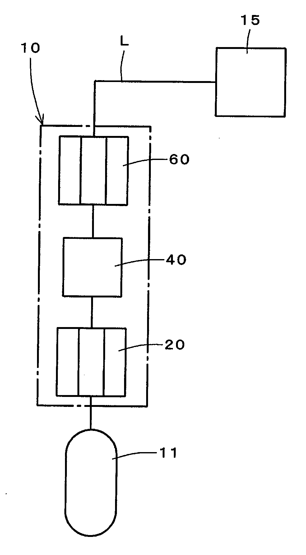
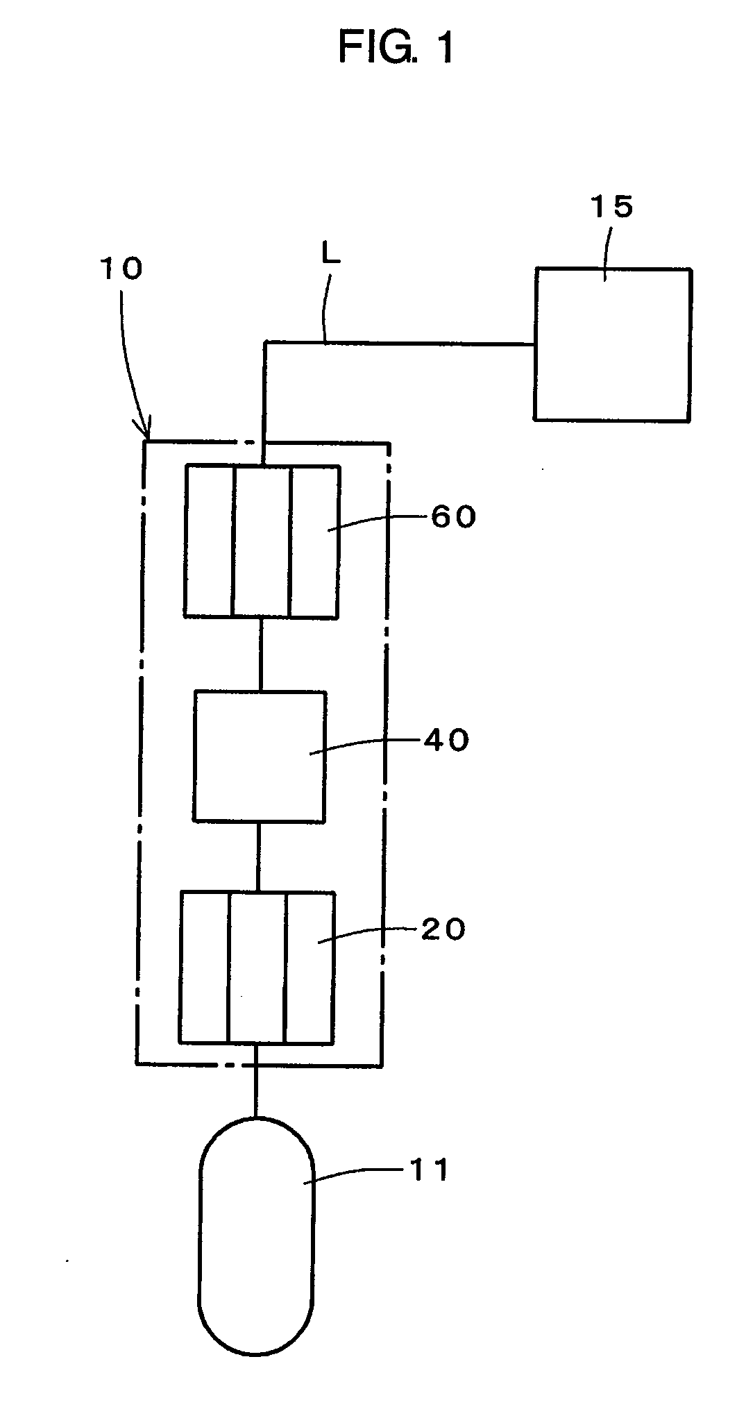
[0025] A flow control system 10 according to the present invention shown in FIG. 1 is arranged at a supply line L of a fluid running from a fluid supply part 11 to a predetermined fluid usage part 15 and includes a first pressure control valve part 20 arranged on the fluid supply part 11 side and a second pressure control valve part 60 arranged on the fluid usage part 15 side through the first pressure control valve part 20 and a pressure loss part 40.

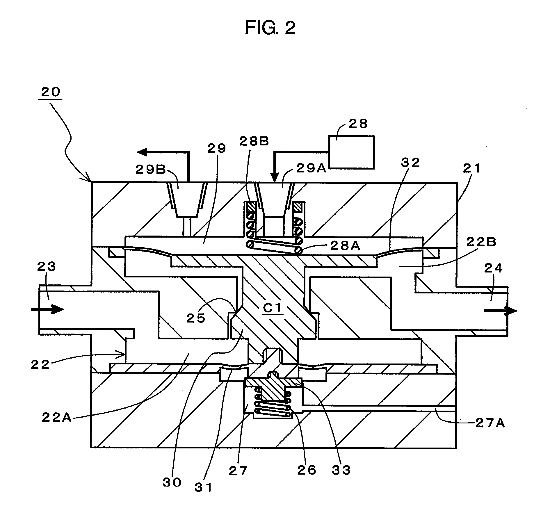
[0026] The first pressure control valve part 20, as shown in FIG. 2, is provided with a first pressure control mechanism C1 maintaining an outlet fluid at a predetermined pressure by a first valve part 30 arranged within a first valve chamber 22 moving back and forth with respect to a first valve seat 25 in accordance with pressure fluctuation of the inlet fluid. Notation 21 in the figure indicates the main body of first pressure control valve part 20, 23 indicates a first opening (inlet port) through which the inlet fluid runs, and 24...

second embodiment

[0041] Further, the configurations of the first pressure control valve part and the second pressure control valve part in the flow control system and their combinations are not limited to only the above embodiments and may be suitably changed. For example, the flow control system of the second embodiment is comprised of a combination of the first pressure control valve part 20 shown in FIG. 2 and a second pressure control valve part 60A shown in FIG. 5. Note that, in the following embodiments, notations the same as with the previous embodiments indicate the same components and their explanations will be omitted.

[0042] The second pressure control valve part 60A, as shown in FIG. 5, is provided with a second pressure control mechanism C3 comprised of the first diaphragm 71 arranged at the valve chamber 62A at the first opening 63 side formed integrally with the second valve part 70A. By arranging the spring 68A as a pressurizing means at the back side of the second pressure control va...

third embodiment

[0044] The flow control system of the invention is comprised of a combination of the first pressure control valve part 20 shown in FIG. 2 and a second pressure control valve part 60B shown in FIG. 6. The second pressure control valve part 60B, as shown in FIG. 6, is provided with the second pressure control mechanism C2 comprised of the first diaphragm 71 arranged at the valve chamber 62A of the first opening 63 side and the second diaphragm 72 arranged at the valve chamber 62B at second opening 64 side formed integrally with the second valve part 70. Further, it is comprised so that it makes the second valve part 70 of the second pressure control mechanism C2 move back and forth with respect to the second valve seat 65 in accordance with the supply of the pressure controlling gas controlled (pressurization) by the electric regulator constituting the pressurizing means 68.

[0045] In the flow control system of the third embodiment comprised as explained above as well, as in the flow c...


PUM


Abstract

A flow control system able to realize stabilization of a flow rate of fluid at a high precision even in cases where pressure fluctuation of an outlet fluid of the flow control system occurs, that is, a flow control system arranged in a supply line of fluid running from a fluid supply part to a predetermined fluid usage part, provided with a first pressure control valve part arranged on the fluid supply part side and a second pressure control valve part arranged on the fluid usage part side through the first pressure control valve part and a pressure loss part, the first pressure control valve part provided with a first pressure control mechanism maintaining the outlet fluid at a predetermined pressure by a first valve part arranged within a first valve chamber moving back and forth with respect to a first valve seat in accordance with pressure fluctuation of the inlet fluid, the second pressure control valve part provided with a second pressure control mechanism maintaining the inlet fluid at a predetermined pressure by a second valve part arranged within a second valve chamber moving back and forth with respect to a second valve seat in accordance with pressure fluctuation of the outlet fluid.

Description

BACKGROUND OF THE INVENTION [0001] 1. Field of the Invention [0002] The present invention relates to a flow control system arranged in a supply line of a fluid running from a fluid supply part to a predetermined fluid usage part. [0003] 2. Description of the Related Art [0004] In the past, as a treatment system used for the purpose of cleaning a silicon wafer etc. in the fields of semiconductor manufacture etc., for example, a batch-type cleaning system has been used (for example, see Japanese Patent Publication (A) No. 2003-86561). In this cleaning system, as shown in FIG. 9, a flow control system 210 having a pressure control valve part 220 provided with a pressure control mechanism maintaining the outlet fluid at a predetermined pressure against pressure fluctuations of the inlet fluid is arranged in a supply line K of fluid running from a fluid supply part 211 to a fluid usage part 215 where a silicon wafer is cleaned. Notation 240 is a flow meter connected to the pressure contr...

Claims


Application Information

Patent Timeline
Patent Type & Authority Applications(United States)
IPC IPC(8): G05D16/06
CPCF16K17/06G05D7/03G05D7/0106F16K31/1268Y10T137/87917H01L21/304
Inventor MATSUZAWA, HIRONORISASAO, KIMIHITO
Owner ADVANCE DENKI KOUGYOU
Why Eureka
Try Eureka