Gas Spring Suspension System

a suspension system and gas spring technology, applied in the direction of shock absorbers, steering devices, cycle equipments, etc., can solve the problems of increasing the length reducing the service life of the upper tube, and increasing the amount of travel needed

Active Publication Date: 2007-03-15
SRAM CORPORATION
View PDF8 Cites 45 Cited by
  • Summary
  • Abstract
  • Description
  • Claims
  • Application Information

AI Technical Summary

Benefits of technology

[0006] In one embodiment of the present invention, the gas spring suspension system is used in a bicycle suspension fork wherein the first tube is a lower tube and the second tube is an upper tube slidable within the lower tube. When the fork is compressed, the volume of the second gas chamber increases and the pressure in the second gas chamber decreases, while the volume of the third gas chamber decreases and the pressure in the third gas chamber increases. If the pressure in the third gas chamber is greater than the pressure in the second gas chamber, the floating piston displaces within the upper tube to equalize the pressures in the second and third gas chambers. This configuration prevents high pressure in the third gas chamber that would prevent the fork from achieving full travel.

Problems solved by technology

However, as riders began to traverse rougher terrain at higher speeds, a greater amount of travel was needed to absorb the higher riding forces.
Typically, a coil spring or an elastomeric suspension fork adds unnecessary weight to the bicycle.
However, a disadvantage of such a gas spring is that during compression the entire length of the upper tube is not used.

Method used


Image

  • Gas Spring Suspension System
  • Gas Spring Suspension System
  • Gas Spring Suspension System

Examples


Embodiment Construction

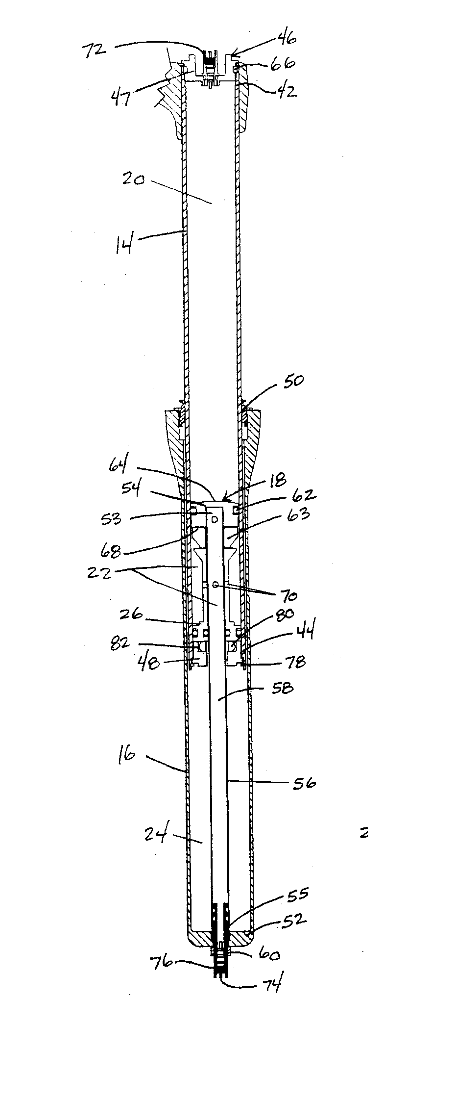
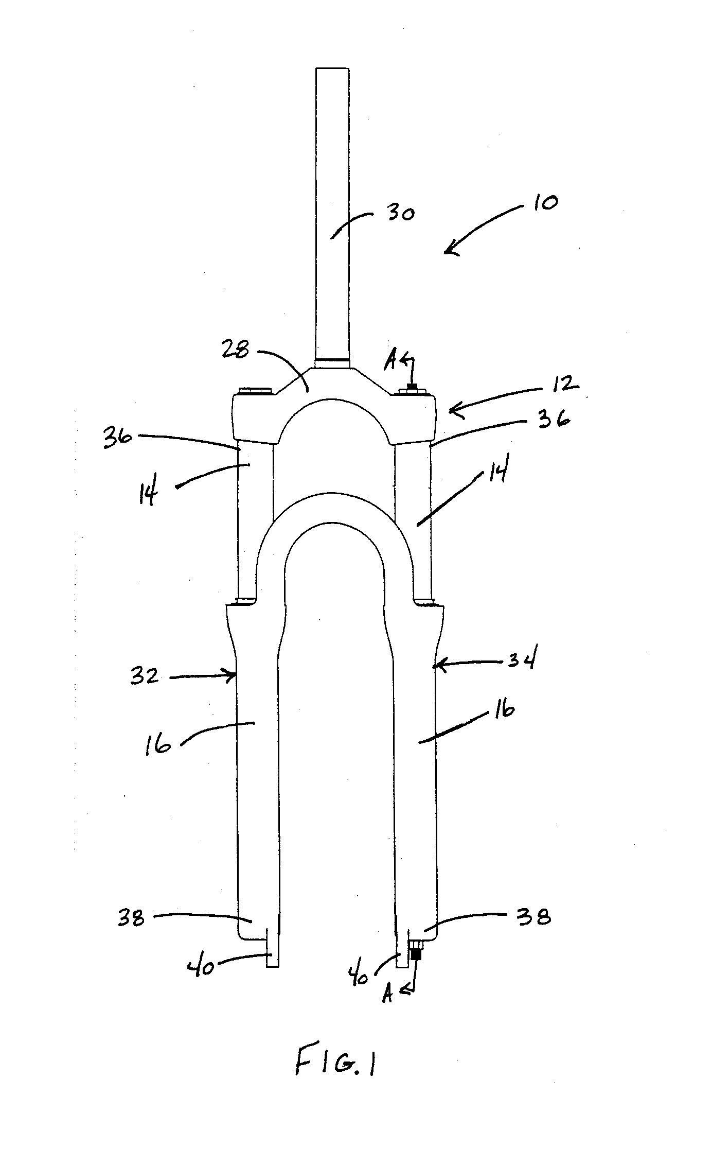
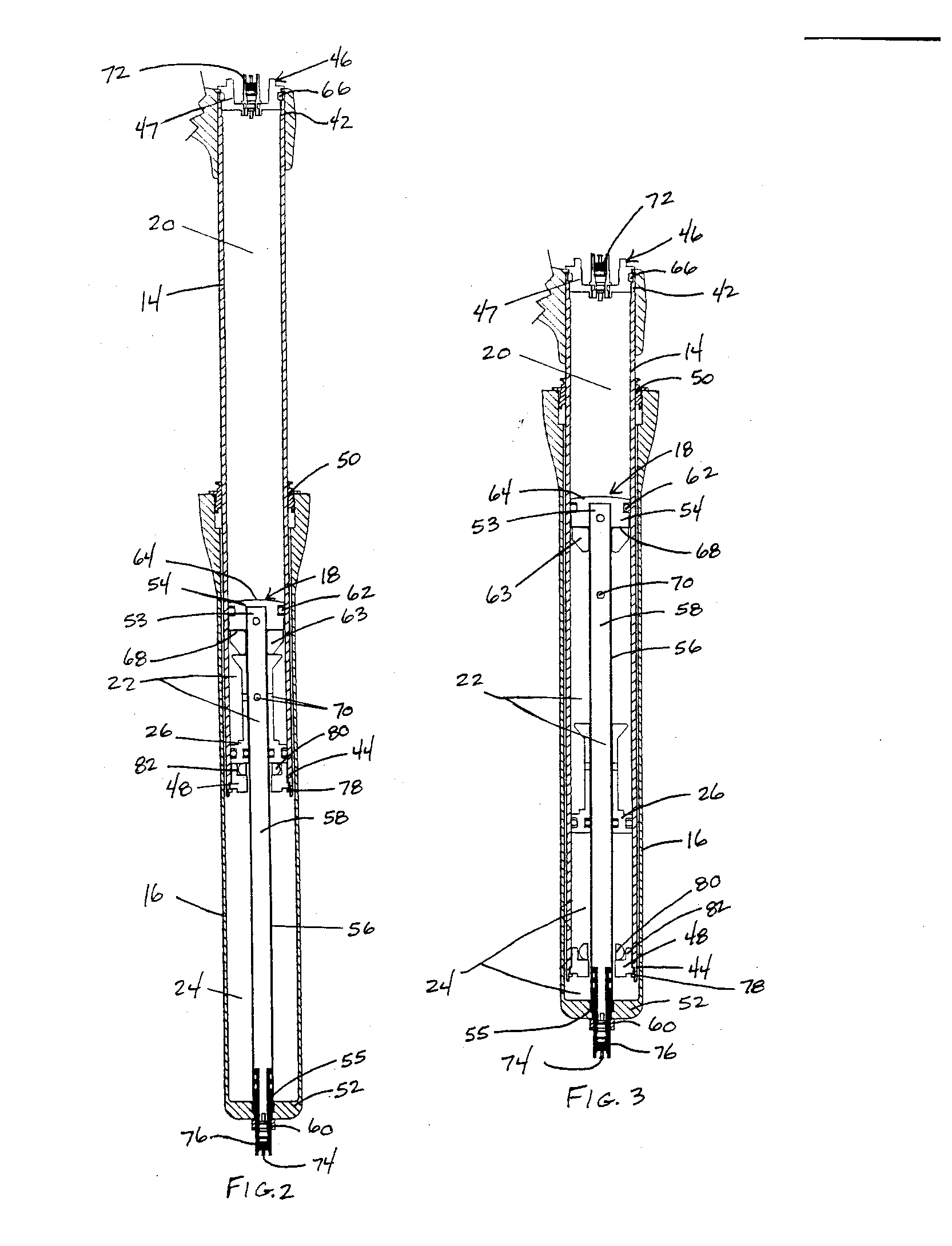
[0013]FIGS. 1-3 illustrate a bicycle front suspension fork 10 that includes a gas spring suspension system 12 in accordance with one embodiment of the present invention. The gas spring suspension 12 generally includes an upper tube 14 slidable in a lower tube 16, a piston assembly 18, first, second and third gas chambers 20, 22, 24 and a floating piston 26 slidably mounted in the upper tube 14. Looking to FIG. 1, the fork 10 includes a crown 28 that is connected to a steerer tube 30, a first leg 32 and a second leg 34. Each of the legs 32, 34 includes the upper tube 14 slidable within the lower tube 16. Alternatively, the lower tube may be slidable within the upper tube. The upper and lower tubes 14, 16 are connected at their remote ends 36 to the crown 28 and at remote ends 38 to a wheel axle (not shown) through dropouts 40. It is to be understood that although the present invention is described with respect to a front suspension fork, the gas spring suspension may be also embodied...


PUM


Abstract

A gas spring suspension system that maximizes the travel of the suspension system. The suspension system includes a first tube and a second tube slidable within the first tube. A piston assembly is slidably mounted in the second tube for changing the pressure in the second tube. A floating piston is slidably mounted in the second tube. A first gas chamber biases the first and second tubes apart from each other while a second gas chamber biases the first and second tubes toward each other. A third gas chamber exists between the floating piston and an end of the first tube. The floating piston has a configuration such that when a pressure in the third gas chamber is greater than a pressure in the second gas chamber, the floating piston displaces within the second tube to decrease the pressure in the third gas chamber.

Description

BACKGROUND OF THE INVENTION [0001] The present invention relates to suspension systems, and more particularly to a gas spring suspension system that includes a floating piston to maximize the travel of the suspension system. [0002] Bicycles include suspension systems to cushion the rider from irregularities in the terrain. Bicycle suspension systems are typically located at the front fork, seat tube or at other bicycle frame locations. A typical front suspension fork includes two legs, each leg having upper and lower telescoping tubes. At least one leg includes a resilient member for biasing the upper and lower tubes apart from each other and for absorbing compressive forces applied to the fork. The resilient member may be a coil spring, an elastomer spring, a gas spring or the like. [0003] The maximum amount the upper and lower tubes may compress relative to each other is commonly referred to as the travel of the fork. Early suspension forks were capable of about 50 mm of travel. H...

Claims


Application Information

Patent Timeline
Patent Type & Authority Applications(United States)
IPC IPC(8): F16F5/00
CPCB62K25/08F16F9/43F16F9/0209
Inventor JORDAN, BRIAN T.
Owner SRAM CORPORATION
Why Eureka
Try Eureka