Eureka AIR delivers breakthrough ideas for toughest innovation challenges, trusted by R&D personnel around the world.

Voltage-controlled oscillator for low-voltage, wide frequency range operation

Active Publication Date: 2007-03-15
APPLE INC
View PDF10 Cites 5 Cited by
  • Summary
  • Abstract
  • Description
  • Claims
  • Application Information

AI Technical Summary

Benefits of technology

[0009] In one embodiment, an apparatus comprises a voltage-controlled oscillator (VCO) that comprises a circuit coupled to receive an input control voltage to the VCO and configured to generate a second voltage responsive to the input control voltage, a summator coupled to receive the input control voltage and the second voltage, and an oscillator coupled to receive the output voltage of the summator. The summator is configured to combine the input control voltage and the second voltage to generate the output v

Problems solved by technology

Unfortunately, a high gain VCO provides large frequency changes in response to small changes in the control voltage, which contributes to the “jitter” experienced on a PLL-generated clock when the clock is phase-locked.
These small changes, in a high gain VCO, may produce undesirable amounts of jitter.
Using multiple VCOs increases the size of the PLL.

Method used


Image

  • Voltage-controlled oscillator for low-voltage, wide frequency range operation
  • Voltage-controlled oscillator for low-voltage, wide frequency range operation
  • Voltage-controlled oscillator for low-voltage, wide frequency range operation

Examples


Embodiment Construction

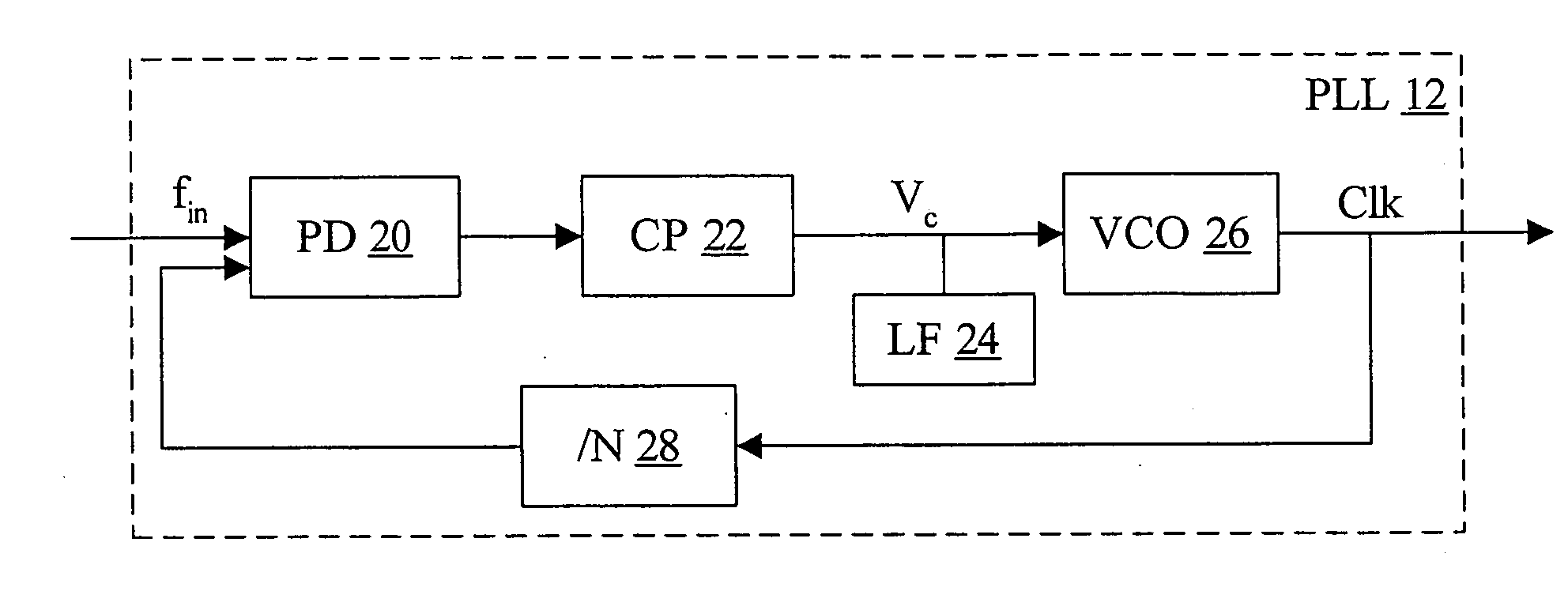
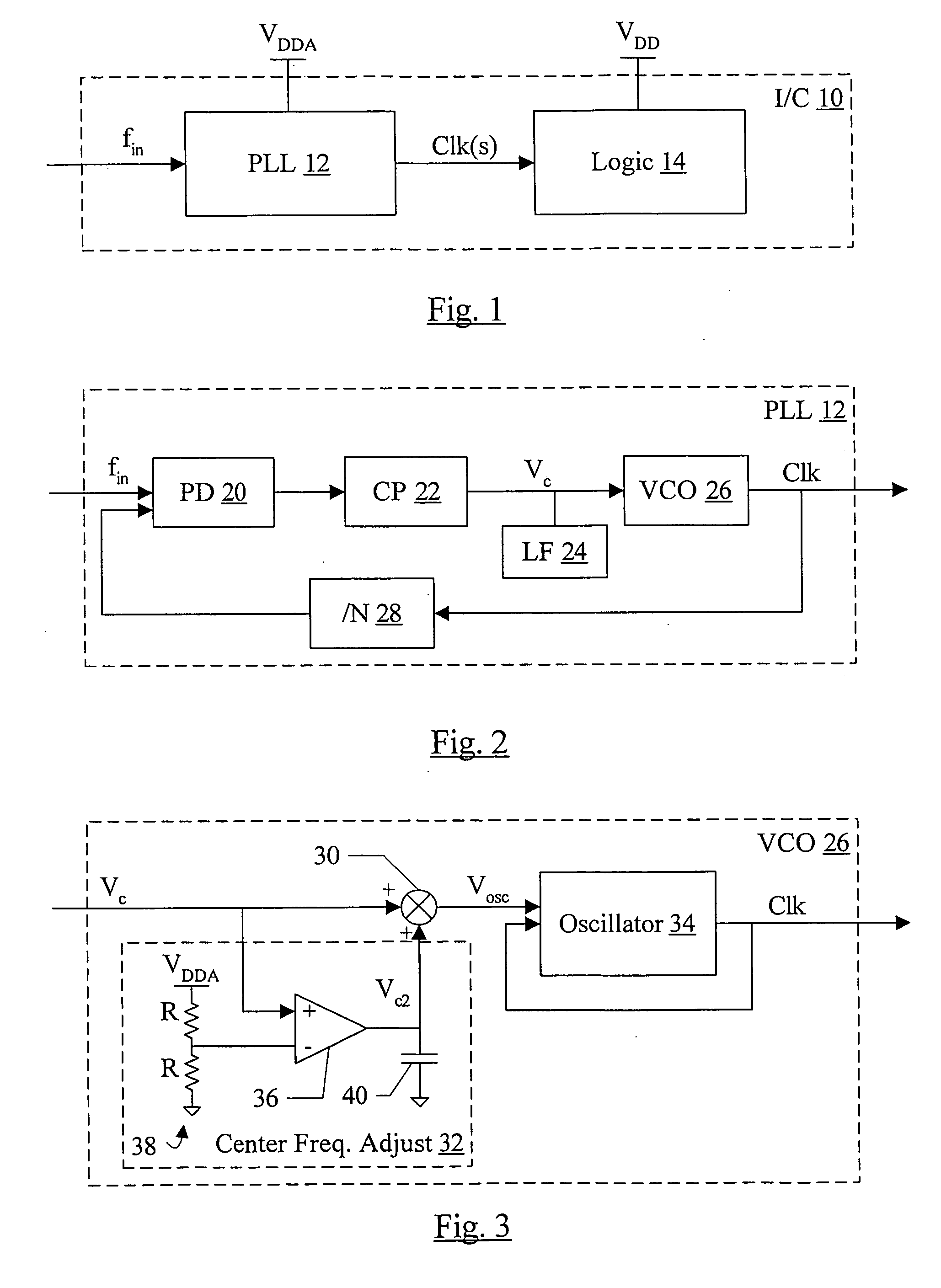
[0020] Turning now to FIG. 1, a block diagram of one embodiment of an integrated circuit (I / C) 10 is shown. In the illustrated embodiment, the integrated circuit 10 includes a PLL 12 and logic circuitry 14. The PLL 12 is coupled to receive a reference frequency (fin) supplied to the integrated circuit 10, and is coupled to provide one or more clocks (Clk(s)) to the logic 14. The PLL 12 is supplied by an analog supply voltage (VDDA), while the logic is supplied by a separate supply voltage (VDD). The VDDA and VDD may have approximately the same magnitude during operation, but a separate analog supply voltage is often provided to insulate the analog circuitry in the PLL from the digital supply voltage. The digital supply voltage is typically noisier due to the high load and large current swings that often occur in digital logic. In the illustrated embodiment, the PLL 12 and the logic 14 are integrated onto a single semiconductor substrate as the integrated circuit 10, although other e...


PUM


Abstract

In one embodiment, an apparatus comprises a voltage-controlled oscillator (VCO) that comprises a circuit coupled to receive an input control voltage to the VCO and configured to generate a second voltage responsive to the input control voltage, a summator coupled to receive the input control voltage and the second voltage, and an oscillator coupled to receive the output voltage of the summator. The summator is configured to combine the input control voltage and the second voltage to generate the output voltage. The oscillator is configured to oscillate an output signal, wherein a frequency of oscillation of the output signal is controlled by the output voltage of the summator.

Description

BACKGROUND [0001] 1. Field of the Invention [0002] This invention is related to the field of voltage-controlled oscillators. [0003] 2. Description of the Related Art [0004] A voltage-controlled oscillator (VCO) comprises circuitry that receives a control voltage and outputs an oscillating signal having a frequency that is controlled by the magnitude of the control voltage. VCOs have a variety of uses in electronics. For example, VCOs are frequently a component of phase-locked loops (PLLs), which are often used to generate clocks in integrated circuits. The output of the VCO is the clock signal used in the integrated circuit, and the control voltage may be generated by other circuitry in the PLL to phase lock the clock signal to an input reference clock. [0005] As the process features (e.g. channel length, oxide thickness, etc.) of integrated circuit manufacturing processes have continued to shrink over time, the magnitude of the supply voltage provided to the integrated circuit has ...

Claims


Application Information

Patent Timeline
IPC IPC(8): H03L7/00
CPCH03L7/0891H03L7/18H03L7/0996H03L7/093
Inventor VON KAENEL, VINCENT R.
Owner APPLE INC
Why Eureka
Eureka Blog
Learn More