Motor controller

a technology of motor controller and controller body, which is applied in the direction of motor/generator/converter stopper, emergency protective arrangement responsive to undesired changes, dynamo-electric converter control, etc., can solve the problem of burning the motor, increasing the size of the entire device, and changing the rotational speed of the motor to increase the error of a computed estimated temperatur

Active Publication Date: 2007-03-15
DENSO CORP
View PDF7 Cites 45 Cited by
  • Summary
  • Abstract
  • Description
  • Claims
  • Application Information

AI Technical Summary

Benefits of technology

[0007] In view of the above-mentioned problems, the object of the present invention is to provide a motor controller that can protect a motor from being burned in an appropriate manne

Problems solved by technology

When the above-mentioned protection element is arranged near the motor, the size of the motor is enlarged, which results in increasing the size of an entire device.
However, when the operating load of the motor is shifted from an assumption range in a design stage by a secular change or the like, the rotational speed of the motor is changed to increase the error of a computed estimated temperature.
However, also in this case, it is likely that because of a difference in power

Method used


Image

  • Motor controller
  • Motor controller
  • Motor controller

Examples


Embodiment Construction

[0018] Hereinafter, an embodiment of the present invention will be described with reference to the drawings. Of course, the construction and the procedure to be described below do not limit the present invention but can be variously modified according to the spirit of the invention.

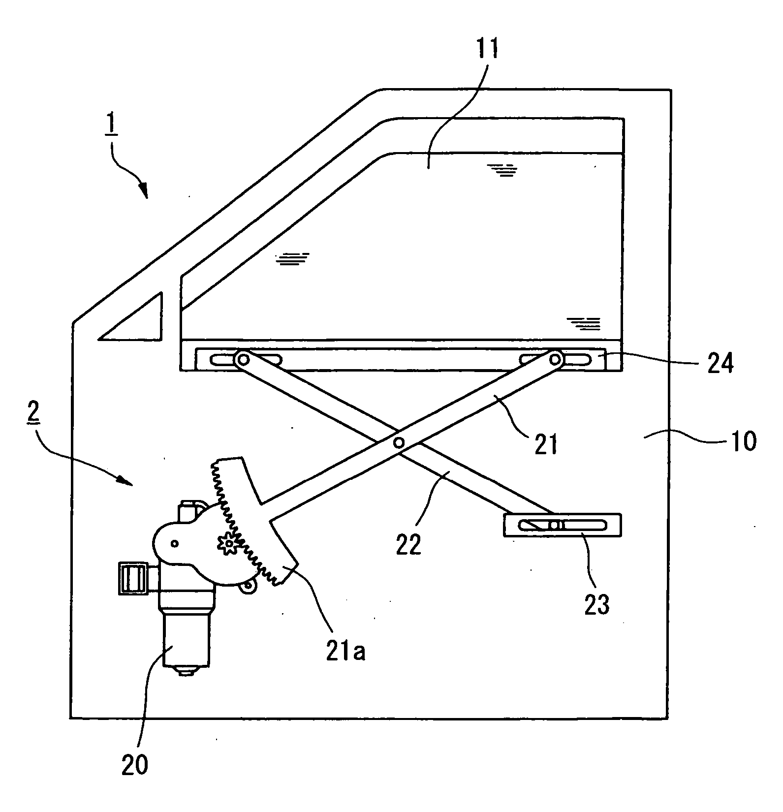
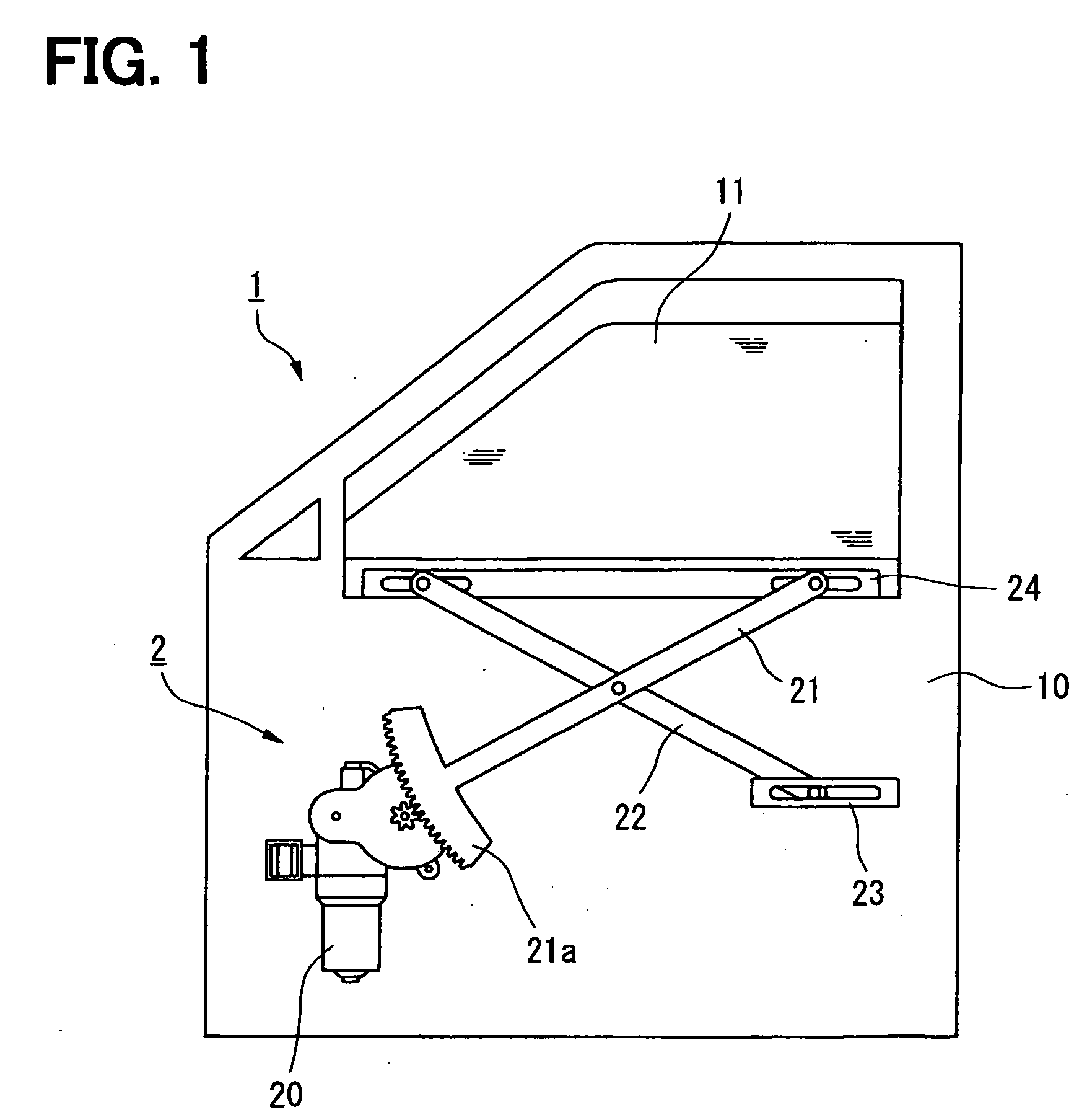
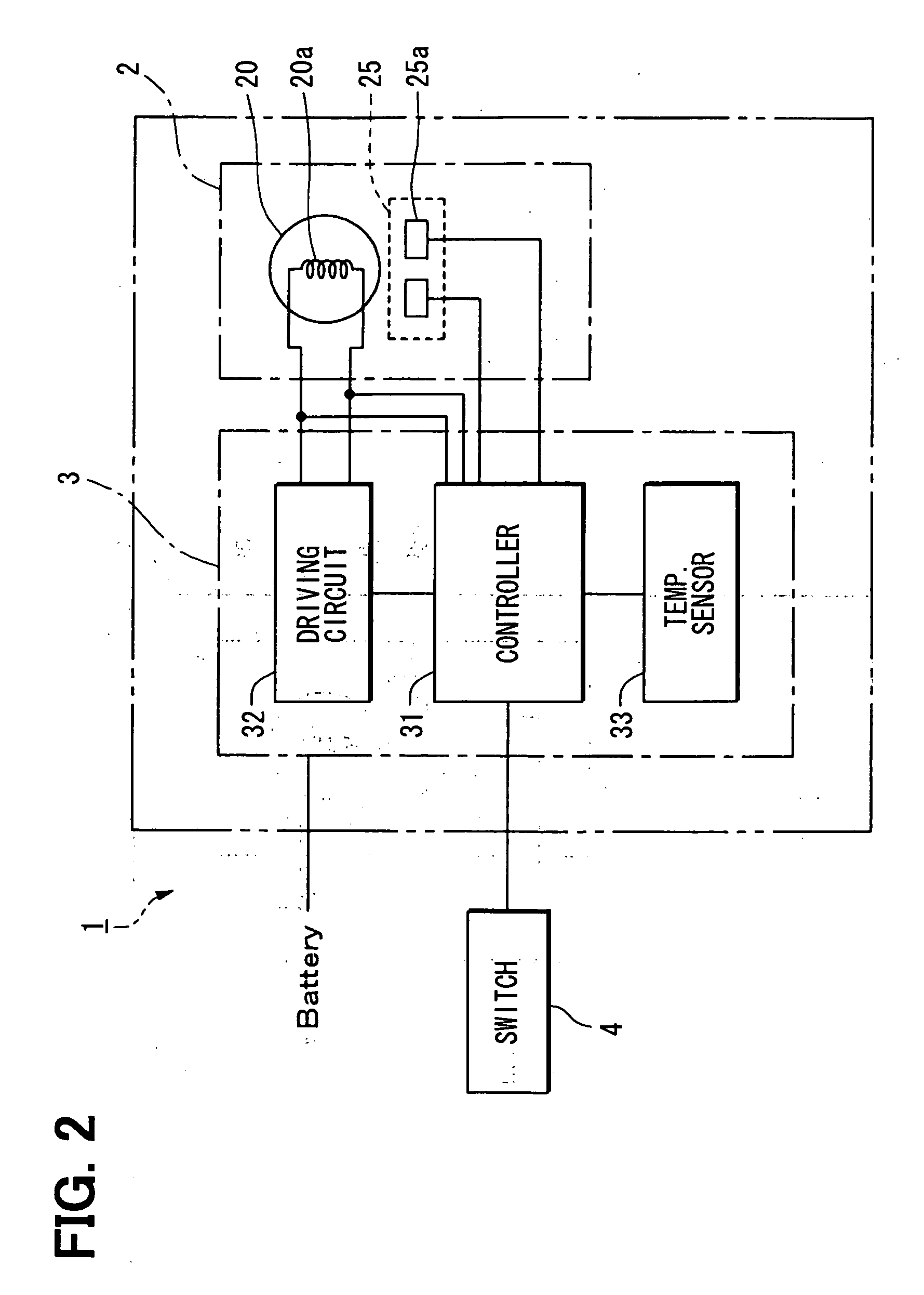
[0019]FIGS. 1-7 are diagrams relating to the embodiment of the present invention. FIG. 1 is an explanatory diagram of a power window device, FIG. 2 is an electric configuration diagram of the power window device in FIG. 1, FIG. 3 is a graph to show the relationship between the rotational speed of a motor and a temperature gradient, FIG. 4 is a graph to show a change in the heat generation temperature of a motor with respect to time, FIGS. 5 and 6 are explanatory graphs to compute a temperature-rise value computing expression, and FIG. 7 is a flow diagram of the processing of computing an estimated temperature of a motor.

[0020] Hereinafter, an example will be described in which the motor controller of th...


PUM


Abstract

A motor controller includes: a motor control part for driving and controlling a motor; an estimated temperature computing part for computing an estimated temperature of a winding of the motor; and a motor protecting part for protecting the motor from being burned when the estimated temperature becomes larger than a predetermined temperature. A temperature rise value of the estimated temperature is computed according to operating conditions of the motor at the time of passing electric current through the winding. This temperature rise value is added to an estimated temperature stored in the estimated temperature storing part to update the estimate temperature. To compute the temperature rise value, an optimum temperature rise value is computed by the use of a plurality of temperature-rise value computing expressions.

Description

CROSS REFERENCE TO RELATED APPLICATION [0001] This application is based upon and claims the benefit of priority of Japanese Patent Application No. 2005-225790 filed on Aug. 3, 2005, the content of which is incorporated herein by reference. FIELD OF THE INVENTION [0002] The present invention relates to a motor controller and, in particular, to a motor controller that has the function of computing an estimated temperature of a motor so as to protect the motor from being burned. BACKGROUND OF THE INVENTION [0003] Conventionally, in order to protect a motor from being burned, a protection element such as a bimetal or a PTC is built in a motor housing. When a motor abnormally generates heat, an electric circuit is interrupted by this protection element and the passing of electric current through the motor is stopped. [0004] When the above-mentioned protection element is arranged near the motor, the size of the motor is enlarged, which results in increasing the size of an entire device. F...

Claims


Application Information

Patent Timeline
IPC IPC(8): H02H5/04H02H5/00H02H6/00H02P29/00H02P29/02
CPCH02H7/0852H02H6/005
Inventor HIRAI, KAZUYUKISUZUKI, TATSUYASHIMOIE, SHINJIWATANABE, SEIICHI
Owner DENSO CORP
Why Eureka
Try Eureka