Interconnection arrangement having mortise and tenon connection features

a technology of interconnection arrangement and mortise, which is applied in the direction of lighting and heating apparatus, instruments, lighting support devices, etc., can solve the problems of limited adaptability of arrangement, no flexibility in the manner in which the light fixture is used, etc., and achieves the effect of reducing the thermal resistance of the junction, high reflection efficiency, and easy to break

Inactive Publication Date: 2007-03-15
INTEGRATED ILLUMINATION SYST
View PDF13 Cites 141 Cited by
  • Summary
  • Abstract
  • Description
  • Claims
  • Application Information

AI Technical Summary

Benefits of technology

[0044] The mortise/tenon configuration lends itself well to this scenario by allowing the connection of a heatsink element (e.g. a finned aluminum body formed by extrusion or the like) via a dovetail that is slid into the mortise and used to absorb and release excess heat from the fixture when the fixture is operating. If deemed necessary, thermal grease can be applied to the dovetail to reduce the thermal resistance of the junction between the dovetail of the heatsink element and the fixture.
[0045] The dovetail equipped heatsink element offers an advantage to inventory management such that fixture manufacturers may stock a single fixture housing and add dovetailed heatsinks as required depending on the required operating ambient temperature of the fixture (i.e. more heat sinking for higher ambients) and wattage of the light source.
[0046] It is should be noted at this point that the fixture/housing should not be taken as being specifically limited to light sources per se and that heating elements, for example, may be disposed in the housing and arranged to direct a beam or beams of infrared radiation (for example) into a room. Indeed, any type of electrical device such as surveillance equipment can be disposed in the housing. Nevertheless, with all type of electrical devices, with highly efficient reflection and/or insulation, still some heat will find its way into the housing and one or more heatsinks can be connected in t

Problems solved by technology

However, these arrangements tend to suffer from the drawback that they are limited in their adaptability.
In fact, many of the mounting features are such that they

Method used


Image

  • Interconnection arrangement having mortise and tenon connection features
  • Interconnection arrangement having mortise and tenon connection features
  • Interconnection arrangement having mortise and tenon connection features

Examples


Embodiment Construction

[0082] An embodiment which is directed to a light fixture will now be described with reference to FIGS. 1-21.

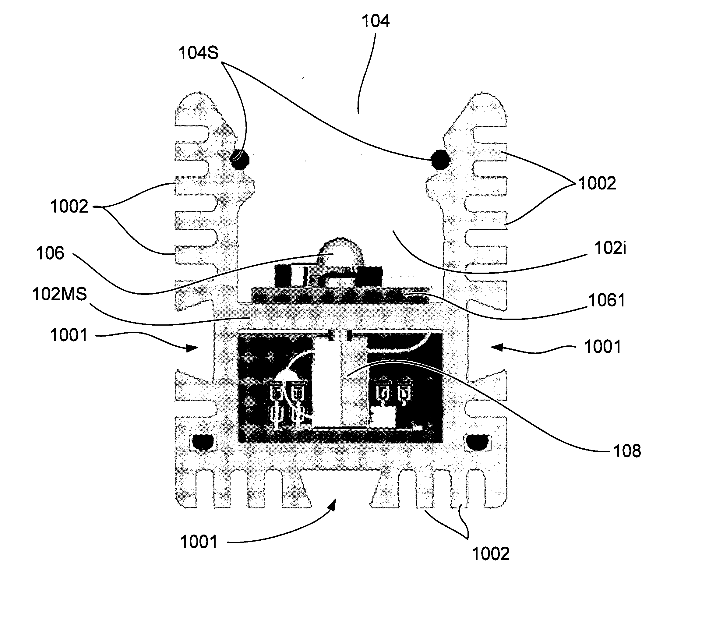
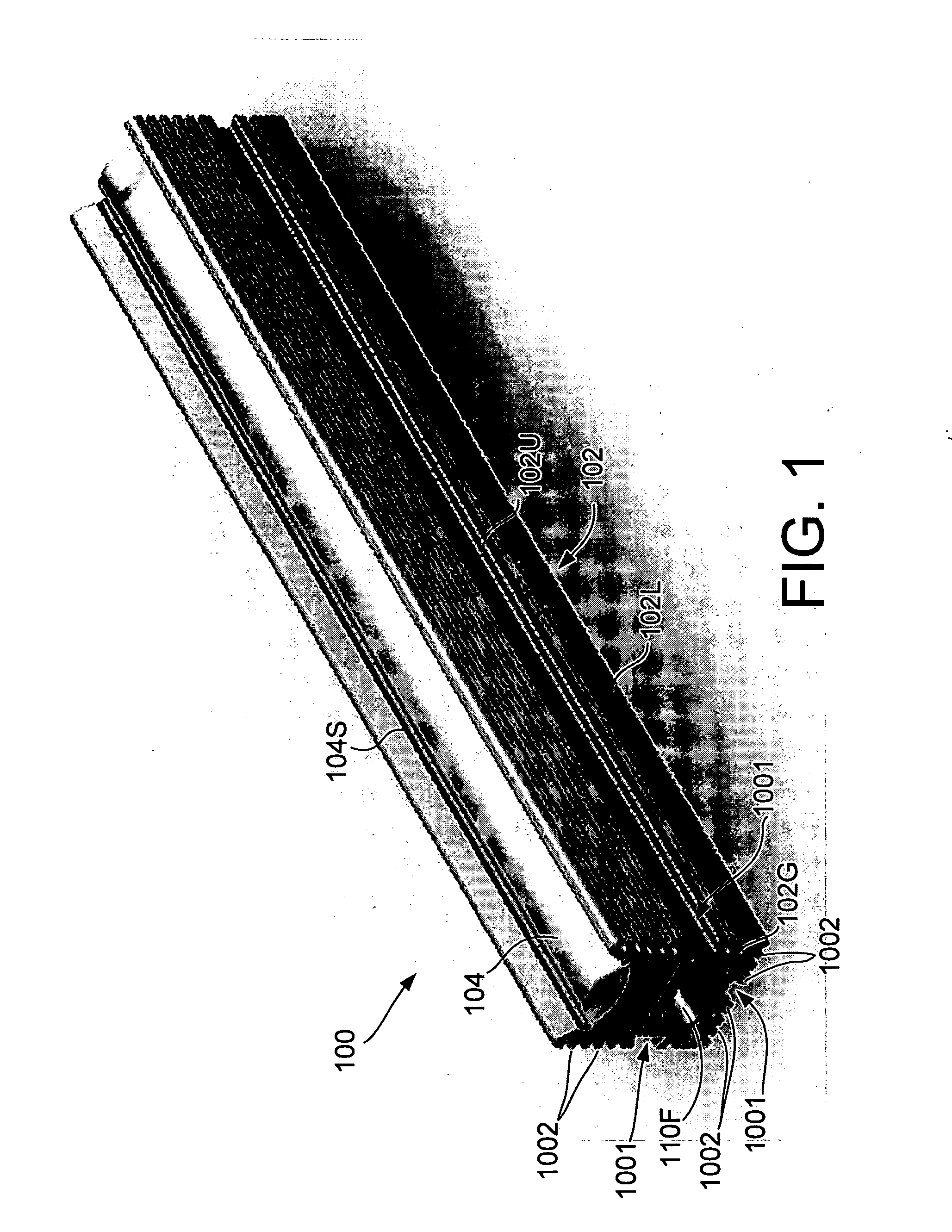
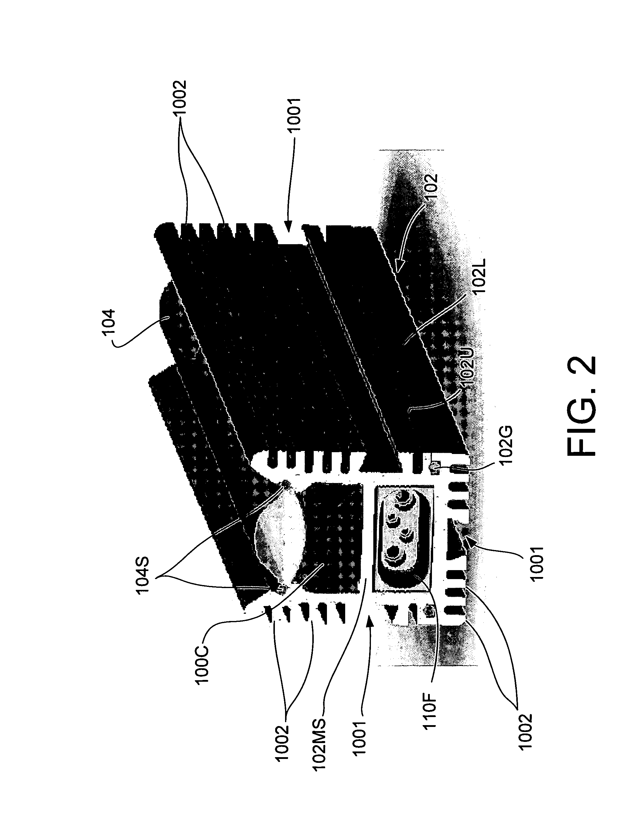
[0083]FIGS. 1-6 depict a light fixture 100 which, in this particular instance, comprises an elongate housing 102, a lens 104, a plurality of light sources in the form of LED 106, current control circuitry 108, and electrical socket / connector(s) 110 for receiving a mating electrical connection member (not illustrated). In this embodiment, the housing 102 comprises upper and lower extrusion members 102U and 102L which are clamped together and sealed via the use of gaskets 102G.

[0084] As best appreciated from FIG. 4 the fixture 100 can be, in one embodiment of the invention, provided at both ends with an electrical socket / connectors 110 and thus allow for a plurality of fixtures 100 to be daisy chained end-on-end in accordance with the length of the final fixture arrangement that is required. These connectors can comprise a female socket member 110F and a male plug member 110M...


PUM


Abstract

An interconnection arrangement features a housing having multiple exterior surfaces. The housing is configured to receive an electrical device therein and has a plurality of the multiple exterior surfaces each having at least one mortise connection feature formed therein which is configured to receive a tenon associated with an accessory and to connect the accessory to the housing.

Description

RELATED APPLICATION [0001] The present invention claims priority from Provisional Application No. 60 / 716,972, filed Sep. 15, 2005, entitled LINEAR LIGHTING UNIVERSAL MOUNTING SYSTEM BASED ON DOVETAIL PRINCIPLES, the disclosure of which is hereby incorporated by reference in its entirety.BACKGROUND OF THE INVENTION [0002] 1. Field of the Invention [0003] The present invention relates generally to a connection arrangement for lighting fixtures and the like, and more specifically to a connection arrangement which is designed to simplify the mounting of fixtures / housings, provide flexibility to the installer of the fixtures / housings, and allow the installer to readily interconnect / interchange selected accessories as required. [0004] 2. Description of the Related Art [0005] Traditionally, linear lighting systems, for example, are used for a variety of applications. Most of these systems use fluorescent light tubes and are available in a variety of sizes, intensities, housings, etc. Furth...

Claims


Application Information

Patent Timeline
IPC IPC(8): F21V19/02
CPCF21S4/008F21V15/013F21V15/015F21V17/104F21V21/005F21V21/02F21V29/767F21V31/005F21Y2101/02F21Y2103/003F21V29/74F21V29/763F21V29/004F21S4/28F21Y2103/10F21Y2115/10F21V17/002
Inventor ZAMPINI, THOMAS L. IIZAMPINI, THOMAS L.ZAMPINI, MARK A.
Owner INTEGRATED ILLUMINATION SYST
Why Eureka
Try Eureka