Image pickup device and image pickup method

a pickup device and image technology, applied in the field of image pickup devices, can solve the problems reducing the light receiving area of the photodiode per pixel, and achieve the effect of shortening the exposure tim

Active Publication Date: 2007-03-15
MAXELL HLDG LTD
View PDF2 Cites 12 Cited by
  • Summary
  • Abstract
  • Description
  • Claims
  • Application Information

AI Technical Summary

Benefits of technology

[0006] As disclosed in JP-A-3-175885, in the case where a standard TV signal is formed from an object by picking up an image thereof in a video camera constituting an image pickup device, the exposure time of the image pickup element built in the video camera is set to substantially the same duration as one field, i.e. the period of the vertical sync signal of the standard TV signal. Nevertheless, it may be desired to lengthen or shorten the exposure time from the one field period for appropriate exposure adjustment.

Problems solved by technology

In recent years, the CCD has been reduced in size with the camera size to such a degree that the light receiving area of the photodiode per pixel is reduced for a lower sensitivity, often resulting in the shortage of light quantity.

Method used


Image

  • Image pickup device and image pickup method
  • Image pickup device and image pickup method
  • Image pickup device and image pickup method

Examples


first embodiment

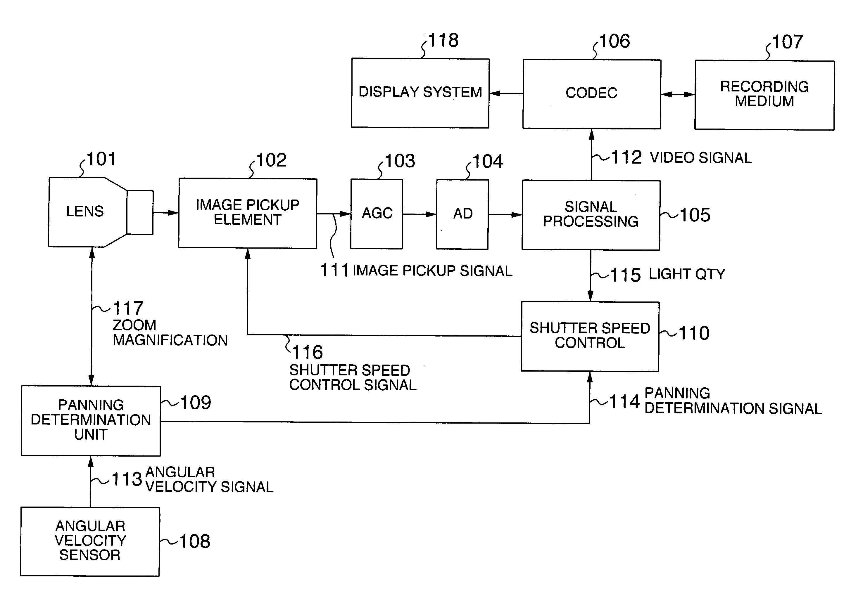
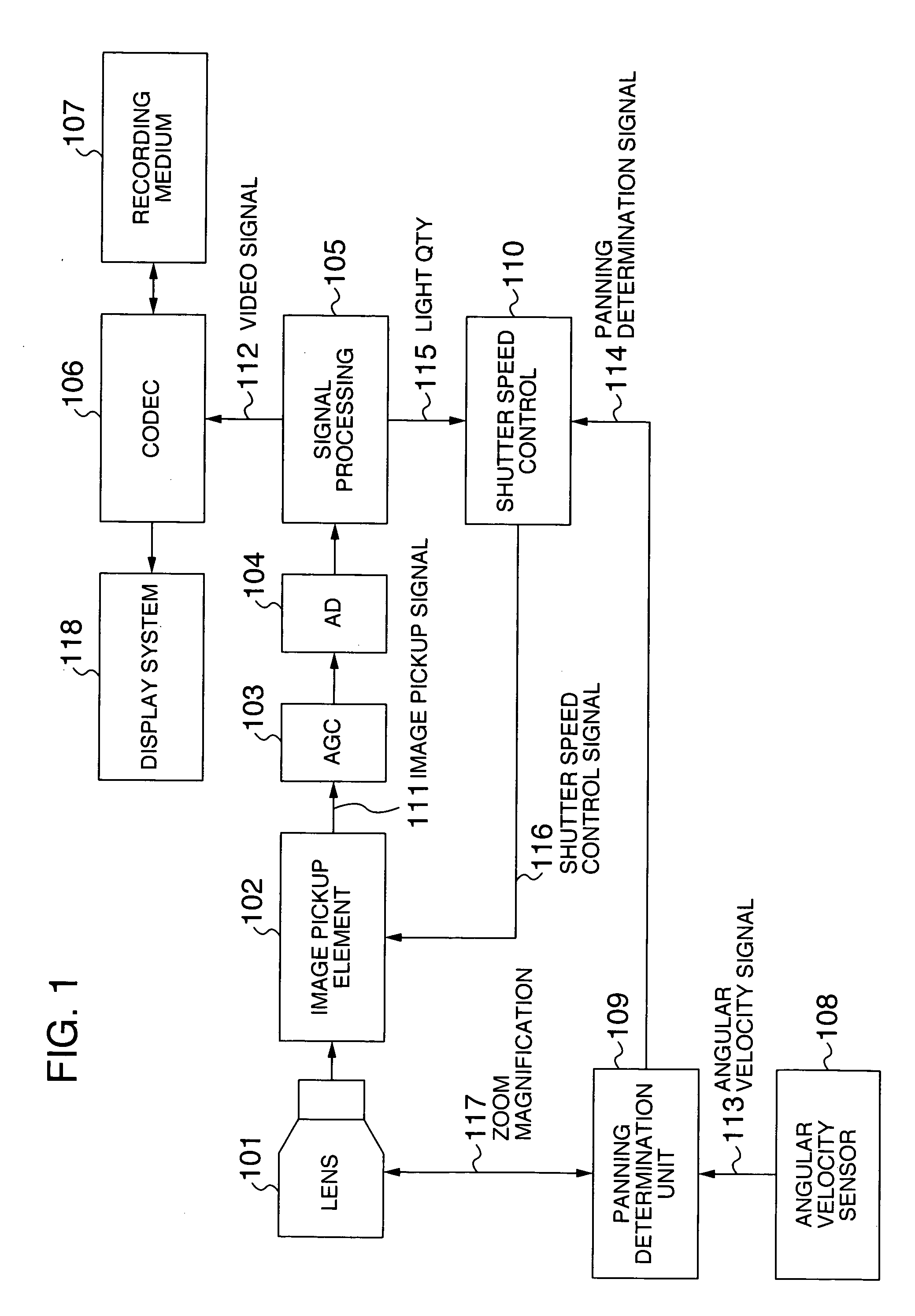
[0024]FIG. 1 is a block diagram showing an application of the image pickup device according to the invention to a video camera. The video camera includes a lens 101, an image pickup element 102 with a changeable shutter speed, an AGC (automatic gain control) circuit 103, an A / D (analog-to-digital) conversion circuit 104, a signal processing circuit 105, a codec (encoder / decoder) 106, a recording medium 107, an angular velocity sensor 108, a panning determination unit 109 and a shutter speed control unit 110.

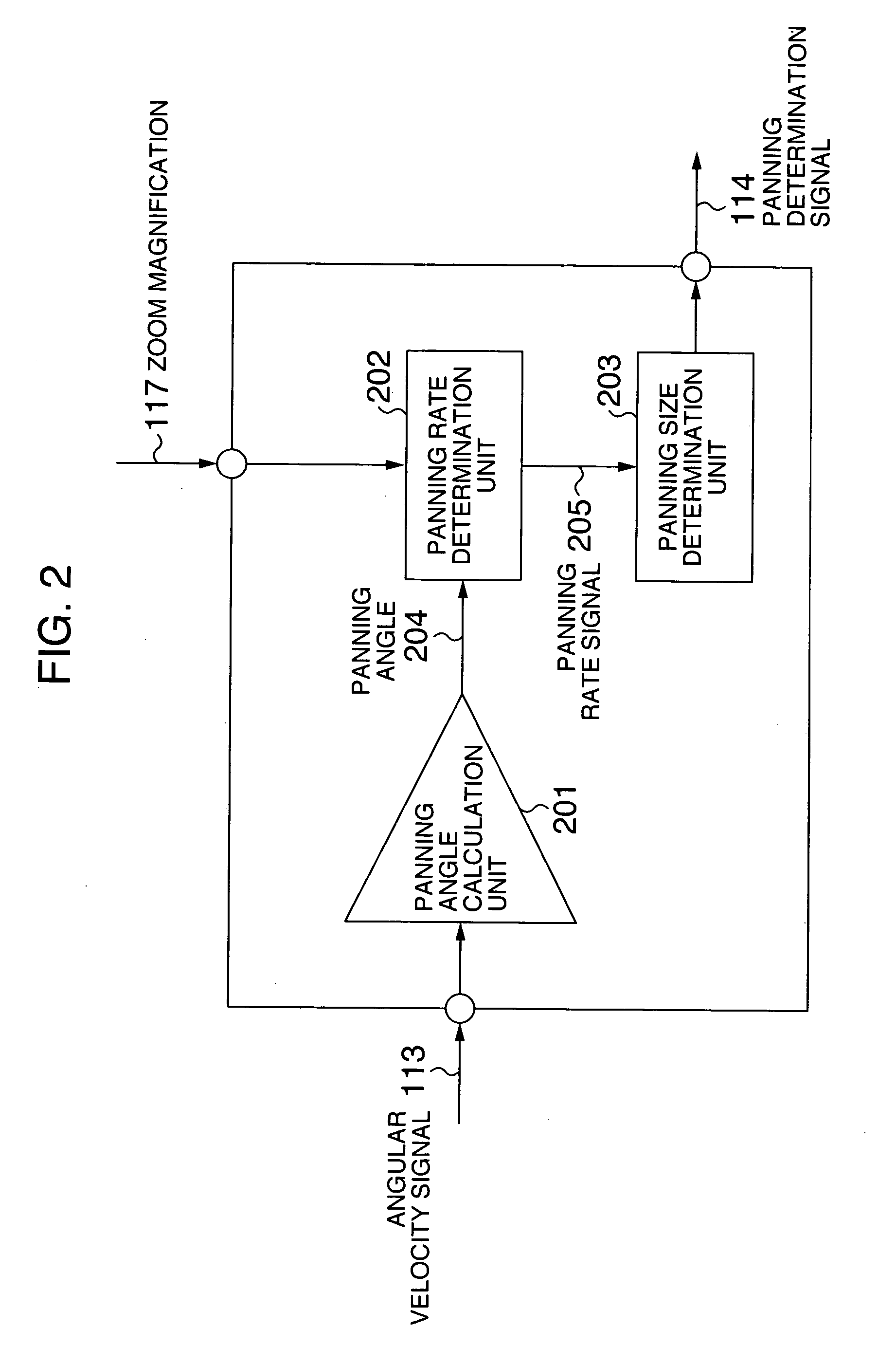
[0025]FIG. 2 is a block diagram for explaining the panning determination unit 109 of FIG. 1 in detail. The panning determination unit 109 includes a panning angle calculation unit 201, a panning rate determination unit 202 and a panning size determination unit 203.

[0026]FIGS. 3A to 3G are diagrams for explaining the views of the image with the shutter speed changed and not changed during the panning operation. In FIGS. 3A-3C, first to fourth motions repeated by first and second...

second embodiment

[0046] An embodiment using the motion vector detection method is explained below with reference to FIGS. 7 and 8.

[0047]FIG. 7 is a block diagram showing the operation for detecting the panning from the motion vector. In place of the angular velocity sensor 108 shown in FIG. 1, the signal processing unit includes a frame memory, and the panning detection means is changed, while the subsequent operation remains unchanged. In the signal processing unit, the video signal processed is stored in the memory, and a newly input image is compared with a previously stored image as a reference image to determine a motion amount and generate a motion vector signal. Specifically, the brightness information for a part of a given object in a previous image is stored in the memory, and whereabouts of the same brightness information in the next incoming image is detected thereby to calculate the motion vector. In the panning determination unit 710, a threshold value is set for the motion vector sign...


PUM


Abstract

An image pickup device and image pickup method are disclosed, wherein an image is picked up by changing the shutter speed in accordance with the illuminance of an object in the case where the rate at which the object moves in the whole image is smaller than a predetermined value, and an image is picked up without changing the shutter speed regardless of the illuminance of the object in the case where the rate at which the object moves in the whole image is not smaller than the predetermined value.

Description

[0001] The present application claims priority from Japanese application JP2005-266219 filed on Sep. 14, 2005, the content of which is hereby incorporated by reference into this application. BACKGROUND OF THE INVENTION [0002] 1. Field of the Invention [0003] This invention relates to an image pickup device capable of controlling the shutter speed. [0004] 2. Description of the Related Art [0005] JP-A-3-175885 contains the description that “Normally in a video camera using a CCD, with the entrance of the light from an object into the CCD, the optical charge corresponding to the strength of the light at the particular portion is generated in a photodiode, which after being accumulated for one field period ( 1 / 60 second), is output as a signal in the next field through a vertical transfer CCD and a horizontal transfer CCD. Specifically, this is equivalent to triggering the shutter in 1 / 60 second. In the case where an image is picked up in a dark place, however, a sufficient signal level...

Claims


Application Information

Patent Timeline
Patent Type & Authority Applications(United States)
IPC IPC(8): G03B7/093G03B7/00H04N5/235H04N5/335H04N5/351H04N5/353H04N5/357H04N5/372H04N5/378
CPCH04N5/23248H04N5/23254H04N5/2353H04N5/2327H04N5/23258H04N23/68H04N23/6811H04N23/6812H04N23/684H04N23/73
Inventor IRINOUCHI, AKIRAMIYAO, HARUHIKO
Owner MAXELL HLDG LTD
Why Eureka
Try Eureka