Battery suitable for preparation of battery module

a battery module and battery technology, applied in the field of batteries, can solve the problems of troublesome and complicated process, high possibility of short circuit, etc., and achieve the effect of reducing the length of connecting members, reducing the inner resistance of the battery module, and improving the structural stability of the battery modul

Active Publication Date: 2007-03-15
LG ENERGY SOLUTION LTD
View PDF4 Cites 19 Cited by
  • Summary
  • Abstract
  • Description
  • Claims
  • Application Information

AI Technical Summary

Benefits of technology

[0034] The arrangement of the unit cells in the lateral direction in the lateral arrangement structure and in the three-dimensional arrangement structure may be accomplished by arranging the unit cells such that the electrode terminals of two unit cells to be electrically connected with each other are adjacent to each other. Consequently, the length of the connecting members is reduced, and therefore, the structural stability of the battery module is improved while the inner resistance of the battery module is reduced. In addition, it is possible to increase the size of the dead space (DS) such that the dead space can be used for various purposes.
[0035] The arrangement of the unit cells in the thickness direction in the three-dimensional arrangement structure may be accomplished by arranging the unit cells such that the battery case surfaces of two unit cells which have no location parts face each other, and, at the same time, the electrode terminals of two unit cells to be electrically connected with each other are spaced apart from each other. According to this arrangement, the electrode terminals of the two unit cells are positioned adjacent to the plane, and therefore, the electrical connection between the electrode terminals is easily accomplished. These electrode terminals are electrically connected with each other, for example, via a bus bar having a step.
[0036] As described above, the battery module according to the present invention may be easily constructed in the three-dimensional arrangement structure. In a preferred embodiment, the battery module includes an integrated frame constructed in a layer structure, and the frame is provided with a plurality of receiving parts, into which a unit cell group having two or more unit cells arranged in the lateral direction and two or more unit cells arranged in the thickness direction can be loaded. Preferably, the loading of the unit cell group into the receiving parts may be performed in a sliding fashion.

Problems solved by technology

In the former case, however, the cathode terminal and the anode terminal are positioned on the same plane, and therefore, the possibility of short circuits is high during the handling of the battery or during the manufacturing of a battery pack.
In the latter case, on the other hand, the possibility of short circuits is higher.
In addition, most of the battery case must be insulated excluding the region used as the electrode terminal, whereby the process is troublesome and complicated.
In this case, a welding process for connection is troublesome and complicated.

Method used


Image

  • Battery suitable for preparation of battery module
  • Battery suitable for preparation of battery module
  • Battery suitable for preparation of battery module

Examples


Embodiment Construction

[0047] Now, preferred embodiments of the present invention will be described in detail with reference to the accompanying drawings. It should be noted, however, that the scope of the present invention is not limited by the illustrated embodiments.

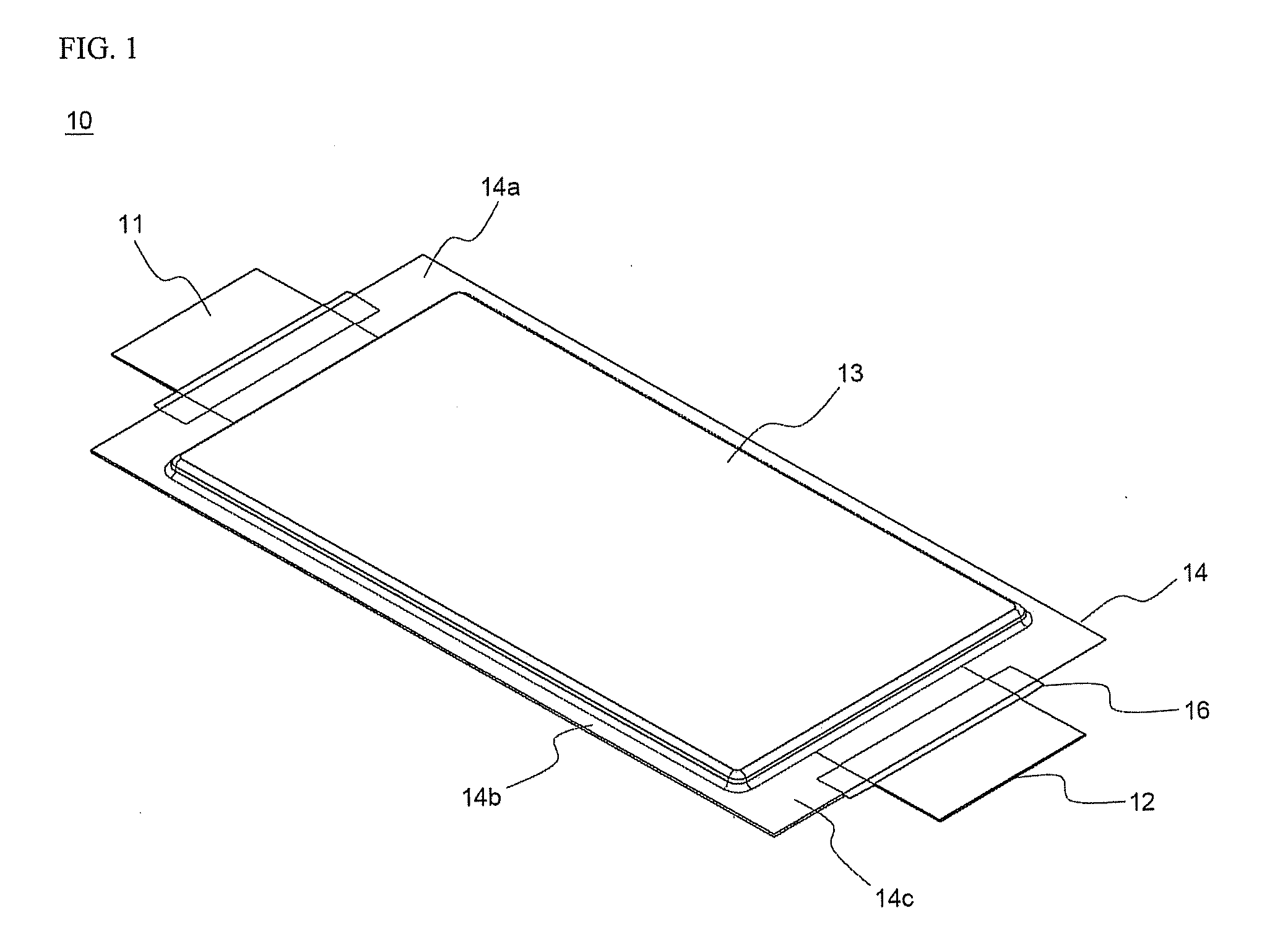
[0048] FIGS. 4 to 6 are a perspective view, a plan view, and a vertical sectional view typically illustrating a battery according to a preferred embodiment of the present invention. The battery shown in these drawings is based on the battery of FIG. 1 in terms of the basic construction of the battery. Consequently, only the difference between the battery according to the present invention and the battery of FIG. 1 will be described below.

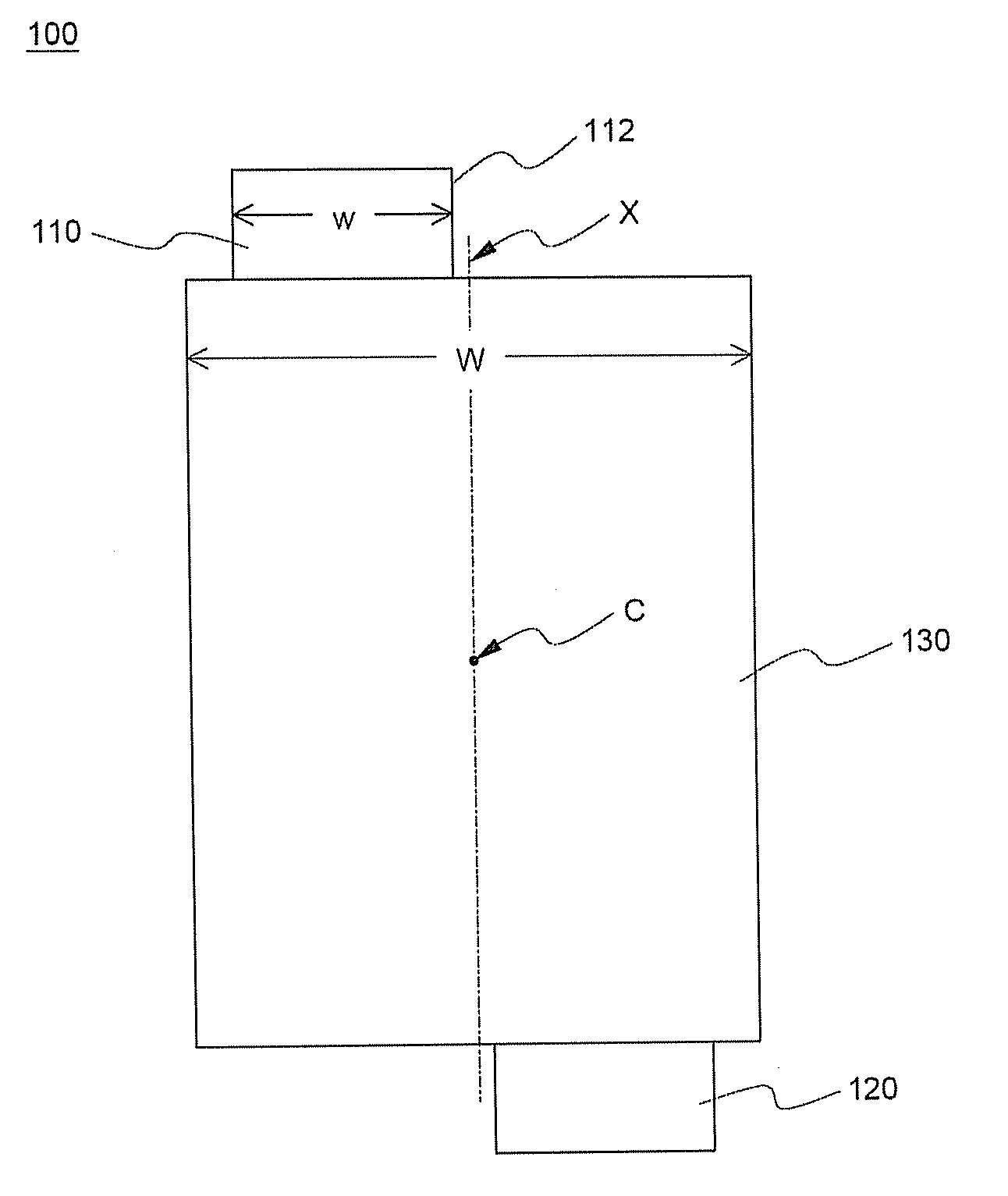
[0049] Referring to these drawings, a battery 100 has two electrode taps 110 and 120, which protrude from the upper and lower ends of a battery cell 130 along the major axis of the battery cell 130. Also, the electrode taps 110 and 120 are deviated from each other about the vertical central axis X on the ...


PUM

PropertyMeasurementUnit
widthaaaaaaaaaa
thicknessaaaaaaaaaa
sizeaaaaaaaaaa

Abstract

Disclosed herein are a battery having an electrode assembly which can be charged and discharged, mounted in a plate-shaped battery case, and cathode and anode terminals protruding from opposite ends of the battery case, wherein the electrode terminals are deviated from each other about the vertical central axis on the plane of the battery cell while the electrode terminals are arranged in a symmetrical fashion, the battery case includes an upper case and a lower case, only one of which is provided with a location part for receiving the electrode assembly, and the electrode terminals are deviated toward the upper or lower case which has no location part on the vertical section of the battery cell, and a battery module including the same.

Description

FIELD OF THE INVENTION [0001] The present invention relates to a battery having electrode terminals formed at opposite ends thereof such that the electrode terminals are deviated from each other, and a battery module including the same. More particularly, the present invention relates to a battery having an electrode assembly, which can be charged and discharged, mounted in a plate-shaped battery case, and cathode and anode terminals protruding from opposite ends of the battery case, wherein the electrode terminals are deviated from each other about the vertical central axis on the plane of the battery cell while the electrode terminals are arranged in a symmetrical fashion, the battery case includes an upper case and a lower case, only one of which is provided with a location part for receiving the electrode assembly, and the electrode terminals are deviated toward the upper or lower case which has no location part on the vertical section of the battery cell, and a battery module c...

Claims


Application Information

Patent Timeline
Patent Type & Authority Applications(United States)
IPC IPC(8): H01M2/02H01M2/06H01M50/211H01M50/224H01M50/227H01M50/231H01M50/505H01M50/528H01M50/548H01M50/553
CPCH01M10/0413H01M2/021H01M6/46H01M2/202H01M2/30H01M2/1077Y02E60/10Y02P70/50H01M50/224H01M50/231H01M50/548H01M50/505H01M50/553H01M50/227H01M50/211H01M50/20
Inventor KIM, KIJAELEE, JIHEON
Owner LG ENERGY SOLUTION LTD
Why Eureka
Try Eureka