
Dental implant system

a technology of implant system and abutment, which is applied in the field of dental implant system, can solve the problems of implant fracturing at the top, failure to completely prevent the rotational displacement of the implant, and space between the coupling surfaces of male and female hexes, and achieve the effect of preventing the rotation of the abutmen

Inactive Publication Date: 2007-03-15
ZICKMAN ALBERT +1
View PDF5 Cites 94 Cited by
  • Summary
  • Abstract
  • Description
  • Claims
  • Application Information

AI Technical Summary

Benefits of technology

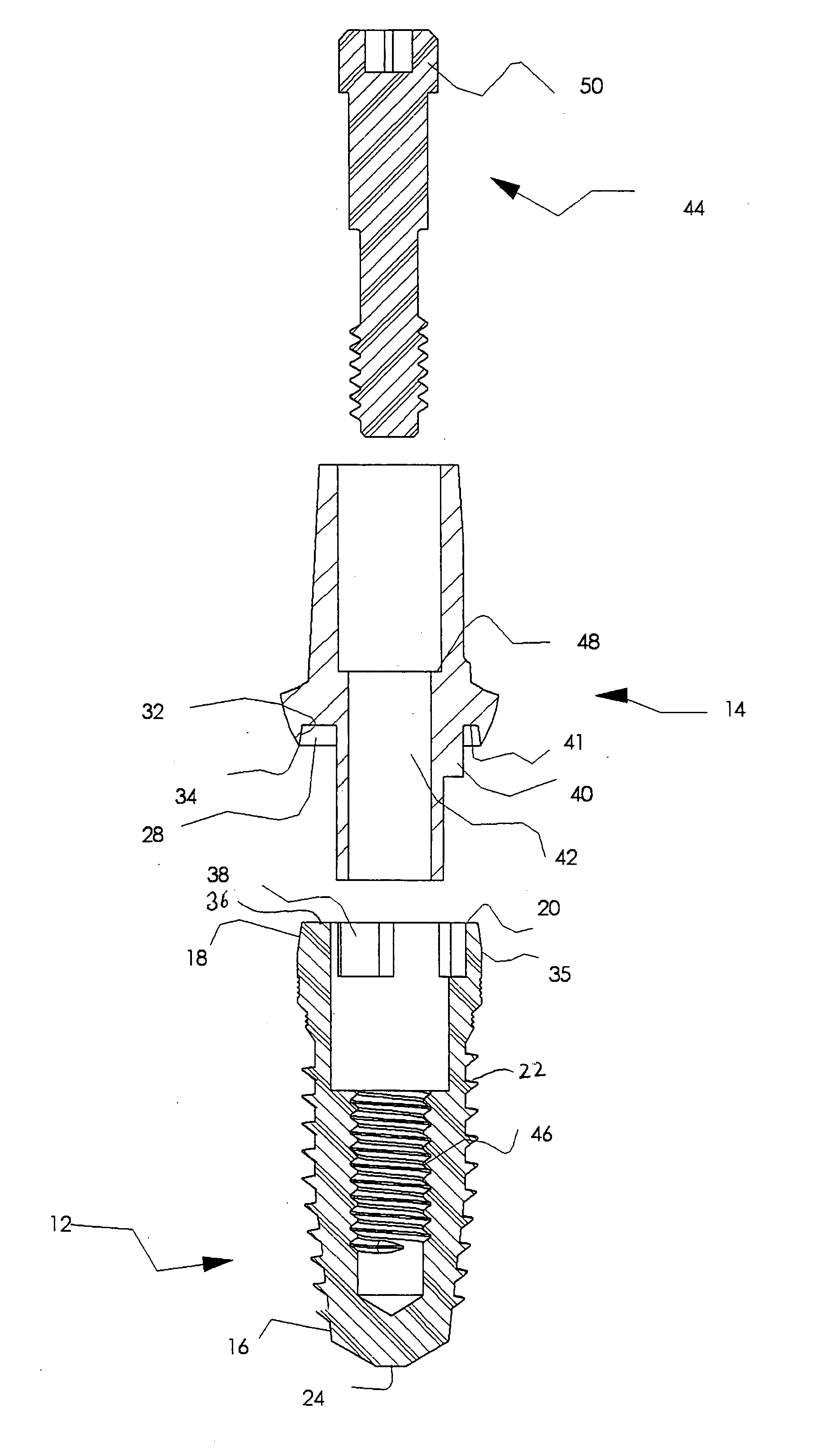
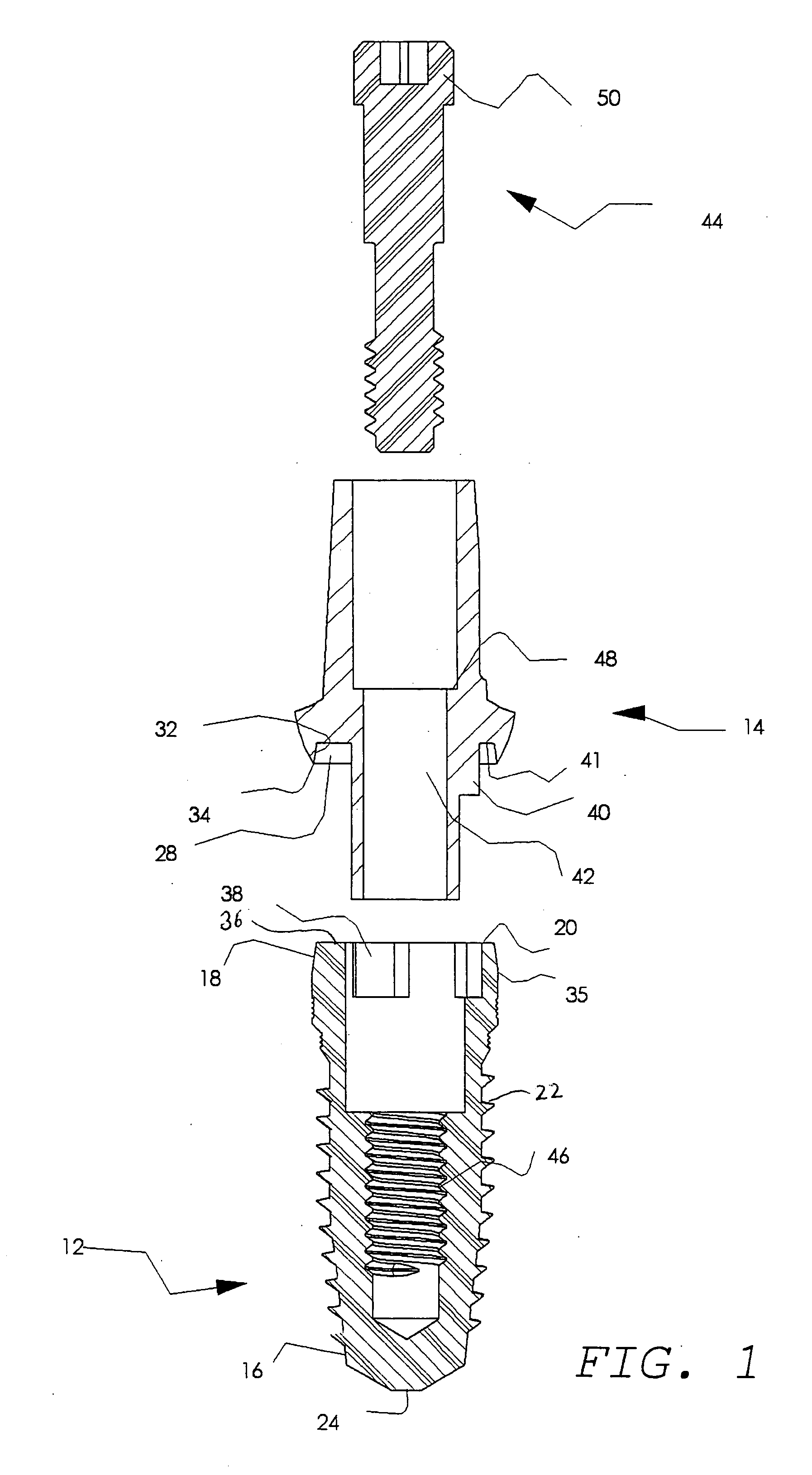
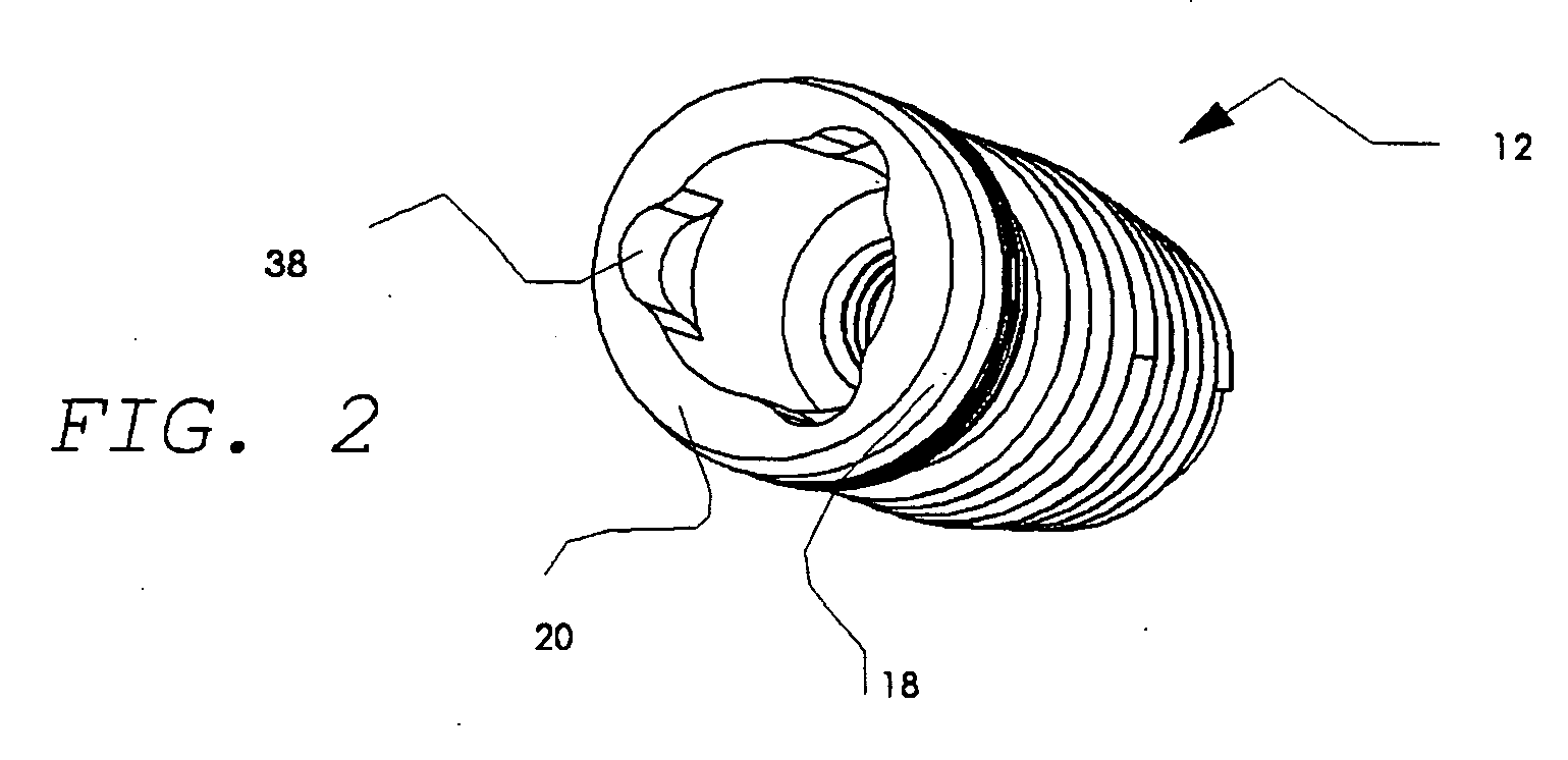
[0012] A dental implant system is provided having an implant body adapted for insertion into a passage formed in a jawbone of a patient, the implant system including an implant body having a top and a bottom end, the implant body having an internally threaded passage and having a connection cavity extending from the top end towards the bottom end, the connection cavity along the top end having an open mouth of a non-circular shape. The system further includes an abutment adapted for use with the implant body, the implant body being removably attached to the abutment, the abutment including a primary cavity and a non-circular projection longitudinally traversing outward from the primary cavity, the projection interlocking with the connection cavity and substantially preventing rotation of the abutment when the abutment is seated on the implant body.

Problems solved by technology

However, this leaves space between the coupling surfaces of the male and female hexes.
However, according to reported studies, the seating of the projection of the abutment within the female cavity of the implant of existing implant system fails to completely prevent rotational displacement of the implant with respect to the abutment.
In addition, there have been multiple reports of implants fracturing at the top because of the force directed against the walls of the internal cavity especially of thin implants with a tri-lobe cavity.
The relative rotation of the abutment and implant result in an attachment that is unstable.
As a result, the screw that joins the implant to the abutment may break or loosen.
This system has the disadvantage that the multisided cavity within the abutment weakens the abutment.
Weakening becomes especially noticeable when the abutment must be cut further to accommodate placement of an adequate crown on top of the abutment; there is an increased risk of abutment fracture.
A further disadvantage of an implant with a projection from its top occurs when an angled abutment must be used.
This scenario can create a problem because the margin of the metal abutment may become visible creating a highly unaesthetic appearance.

Method used


Image

  • Dental implant system
  • Dental implant system
  • Dental implant system

Examples


Embodiment Construction

[0030] The present invention will now be described more fully hereinafter with reference to the accompanying drawings, in which preferred embodiments of the invention are shown. This invention may, however, be embodied in many different forms and should not be construed as limited to the embodiments set forth herein; rather, these embodiments are provided so that this disclosure will be thorough and complete, and will fully convey the scope of the invention to those skilled in the art.

[0031] Referring now to FIGS. 1-4, shown is a multi-part, endosseous dental implant system. It should be understood that common components of the various embodiments for practicing the instant invention retain the same numerical designation in each of the Figures. The dental implant system has an implant body, generally designated by the reference numeral 12 (FIGS. 1, 2, 4-11 and 13) and an abutment, generally designated by the reference numeral 14 (FIGS. 1, 3, 4 and 12).

[0032] With reference now to ...


PUM


Abstract

An endosseous implant system is provided having an implant body and an abutment. The implant body has a connection cavity at a top end of the implant body, the connection cavity having an open mouth of non-circular shape. The abutment has a primary cavity and a projection oriented along a longitudinal axis of the abutment, the projection protruding outward away from the primary cavity and forming an anti-rotational junction with the connection cavity of the implant.

Description

[0001] This application claims priority from U.S. Provisional Patent Application Ser. No. 60 / 717,566, filed Sep. 15, 2005, titled “Dental Implant.”FIELD OF THE INVENTION [0002] This invention relates to a dental implant system. More particularly, this invention relates to a dental implant system having an implant body and an abutment, wherein the implant body and abutment form at least a first anti-rotational connection by frictional engagement of mating tapered surfaces and a second-anti-rotational connection between a projection at the bottom of the abutment and a cavity of the implant. BACKGROUND OF THE INVENTION [0003] Two-part endosseous dental implant systems for insertion in a wholly or partially edentulous region of the jawbone of a patient are known in the art. The implant system may be completely embedded in a jawbone of a patient. Typically, a protective cover screw is attached to the top of the implant. The implant is then covered with mucosal tissue. Alternatively, the ...

Claims


Application Information

Patent Timeline
IPC IPC(8): A61C8/00
CPCA61C8/005A61C8/0054A61C8/0059A61C8/0089A61C8/0066A61C8/0068A61C8/006
Inventor ZICKMAN, ALBERTLERNER, SHELDON
Owner ZICKMAN ALBERT
Learn More