Radio communication apparatus

a radio communication and apparatus technology, applied in the field of radio communication, can solve problems such as the likely deterioration of the entire system in throughpu

Inactive Publication Date: 2007-03-15
KK TOSHIBA
View PDF7 Cites 20 Cited by
  • Summary
  • Abstract
  • Description
  • Claims
  • Application Information

AI Technical Summary

Benefits of technology

[0028]FIG. 14 is a view for explaining time ratio control between a 20M_ch period

Problems solved by technology

If each length of the communication periods is set inappropria

Method used


Image

  • Radio communication apparatus
  • Radio communication apparatus
  • Radio communication apparatus

Examples


first embodiment

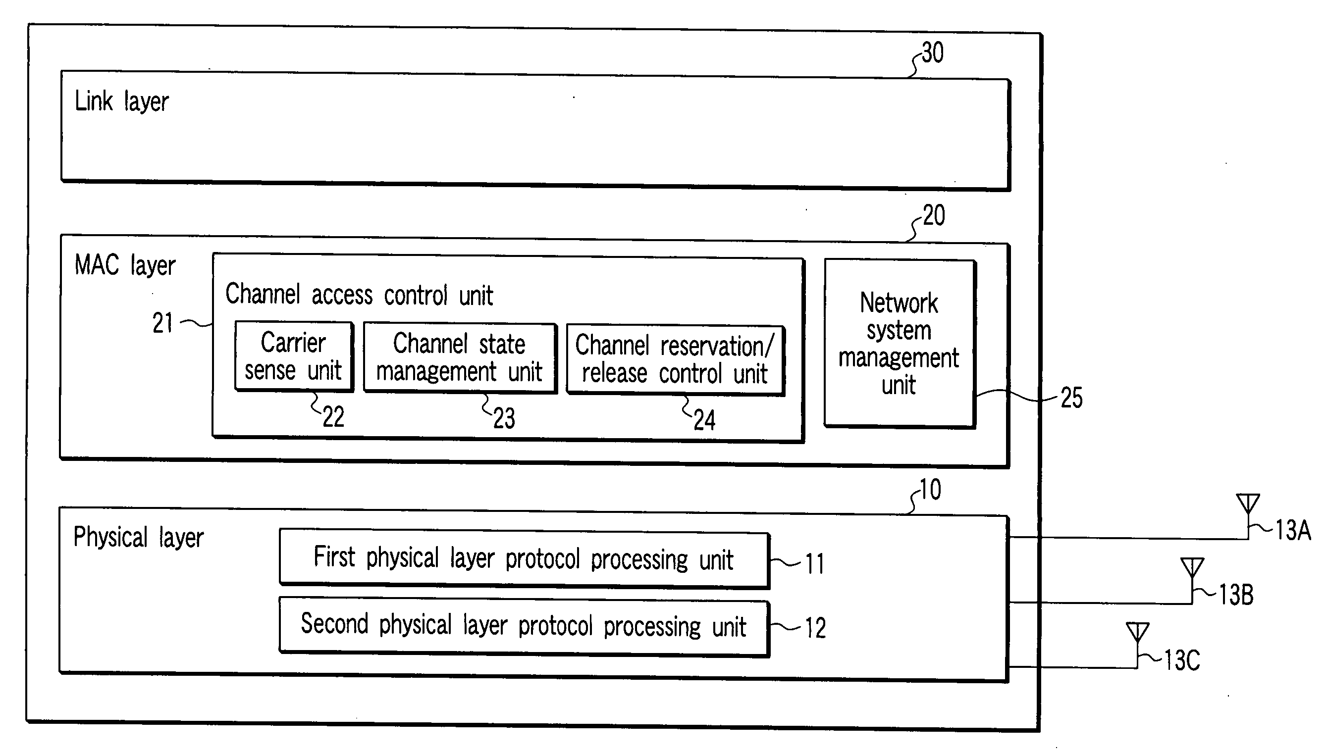
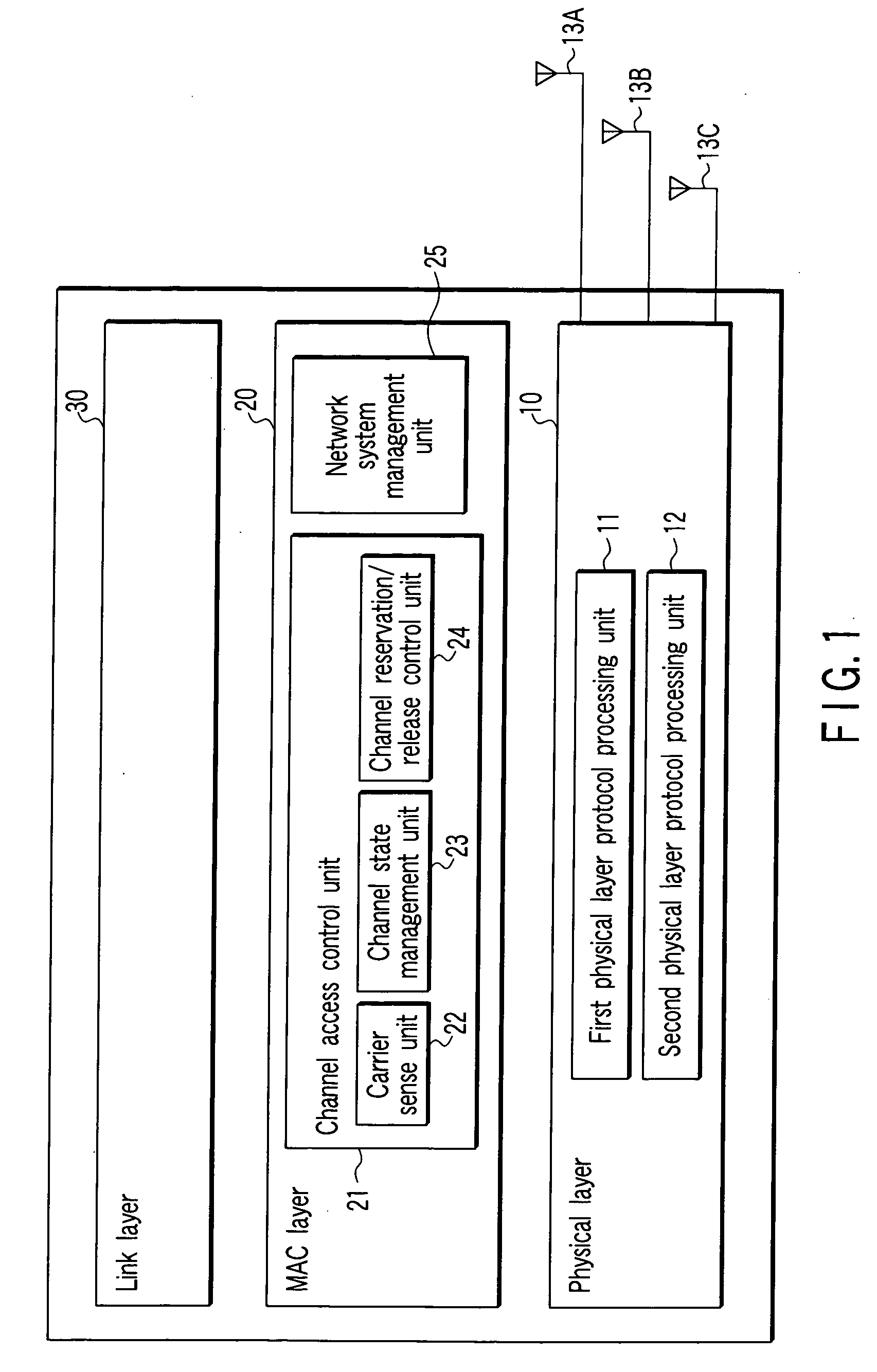
[0031]FIG. 1 shows a configuration of a terminal according to the first embodiment. As shown in FIG. 1, a radio communication apparatus according to the first embodiment mainly comprises a PHY layer 10, a MAC layer 20 and a link layer 30. In FIG. 1, the PHY layer corresponds to two kinds of PHY layer protocols differing in frequency bandwidth of channels to be used. That is, the PHY 10 has a first PHY layer protocol processing unit 11 to perform PHY layer protocol processing for communicating by use of a first channel having a first communication bandwidth; and a second PHY layer protocol processing unit 12 to perform PHY layer protocol processing for communicating by use of a second channel having a second communication bandwidth. Practically, the first and the second processing units 11 and 12 frequently share a circuit therebetween and they are not always independent from each other.

[0032] The protocol to be processed by the first processing unit 11 includes at least the PHY lay...

second embodiment

[0085] Because a second embodiment is basically similar to the first embodiment, the second embodiment will be intensively described the point deferring from the first embodiment. The different point is that the first embodiment assumes to control the 20M_ch period and 40M_ch period depending on the number of the STAs but the second embodiment controls them by traffic amounts not by the number of the STAs.

[0086] The AP firstly collects information on a data amount stored in transmission queues of each STA. Here, we will describe the case of a wireless LAN system using the standard of IEEE 802.11e as an example. Each STA compliant with IEEE 802.11e standard describes size of transmission data (transmission queue size) actually stored in a QoS control field to transmit data frames. The AP collects sizes of the transmission queues from the data frames transmitted from each STA to grasp transmission data amounts stored in each STA.

[0087] For using a polling system such as an HCF contr...

third embodiment

[0098] Since a third embodiment is basically similar to the first embodiment, the third embodiment will be selectively described the point deferring from the first embodiment. The different point is that the first embodiment assumes to control the 20M_ch period and 40M_ch period depending on the number of the STAs but the third embodiment controls them by channel states. The channel state in the third embodiment means, for example, presence or absence of interference from other communications which are detected in scanning the channel state.

[0099]FIGS. 12A and 12B show examples of determining the time ratios between the 20M_ch period and 40M_ch period depending on channel states, respectively.

[0100]FIG. 12A shows the case in which the AP detects interference at a fixed cycle on the channel 20M_ch_b in channel scanning. Such an interference source is a radar. Assuming that the AP makes the 40 MHz communication using both the channels 20M_ch_a and 20M_ch_b during a period in which i...


PUM


Abstract

A radio communication apparatus includes an acquiring device which acquires information required to determine a ratio between a first period length making a radio communication by using either of two first channels each having a first bandwidth and a second period length making a radio communication by using a second channel having a second bandwidth wider than the first bandwidth. The second channel is overlapping with the two first channels. A determining device determines the ratio on the basis of the information, thereby determines the first period length and the second period length. Accordingly, a radio communication by using the first channel within the first period length and a radio communication by using the second channel within the second period length are performed.

Description

CROSS-REFERENCE TO RELATED APPLICATIONS [0001] This application is based upon and claims the benefit of priority from prior Japanese Patent Application No. 2005-267028, filed Sep. 14, 2005, the entire contents of which are incorporated herein by reference. BACKGROUND OF THE INVENTION [0002] 1. Field of the Invention [0003] The present invention relates to a radio communication to perform media access control (hereinafter, refereed to as MAC) on the basis of a carrier sense state, and more particularly to a radio communication in which a plurality of users share a plurality of channels. [0004] 2. Description of the Related Art [0005] The MAC controls to decide how a plurality of communication apparatuses communicating by sharing the same media should use media and transmit communication data. With the MAC is performed, a phenomenon (so-called collision) that a communication apparatus on a reception side becomes impossible to separate the communication data is reduced even when more t...

Claims


Application Information

Patent Timeline
IPC IPC(8): H04Q7/20H04L12/28H04W16/02H04W72/02H04W72/04H04W72/10H04W74/08H04W76/02H04W84/12
CPCH04W72/085H04W74/0875H04W72/10H04W72/542H04W72/56
Inventor UTSUNOMIYA, YORIKOADACHI, TOMOKOTAKAGI, MASAHIRONAKAJIMA, TETSUTANDAI, TOMOYA
Owner KK TOSHIBA
Why Eureka
Try Eureka