Fully-threaded bioabsorbable suture anchor

a fully-threaded, suture technology, applied in the field of surgical suture anchoring apparatus and methods, can solve the problems of suture being easily suture being detached from the anchor prematurely, suture being exposed to abrasion or cutting, etc., to achieve the effect of increasing the pullout strength of suture, and reducing the risk of injury

Active Publication Date: 2007-03-15
ARTHREX
View PDF19 Cites 377 Cited by
  • Summary
  • Abstract
  • Description
  • Claims
  • Application Information

AI Technical Summary

Benefits of technology

[0008] The internal loop preferably extends through more than half the length of the fully-threaded central body and forms an eyelet at the proximal end. The loop is located at least partially within the drive socket. Multiple sutures for tying down tissue may be looped through the loop, allowing the sutures to slide smoothly with minimal friction. In a preferred embodiment of the invention, the ends of the internal loop are tied together to form at least one knot which is housed in a recessed region provided at the distal end of the anchor body. The knot increases the pullout strength of the suture even in soft bone, provides increased suture fixation, and eliminates the anchor “pull back.”

Problems solved by technology

Problems can arise if the structure for attaching the suture fails, allowing the suture to become detached from the anchor.
Also, the suture often is exposed to abrasion or cutting by sharp or rough areas along the walls of the bone canal into which the anchor is inserted.
As a result, suture attached to the eyelet is vulnerable to abrasion by the bony rim of the countersunk hole into which the suture anchor is installed.
In addition, in biodegradable prior art devices, the eyelet can degrade rapidly, causing the suture to become detached from the anchor prematurely.

Method used


Image

  • Fully-threaded bioabsorbable suture anchor
  • Fully-threaded bioabsorbable suture anchor
  • Fully-threaded bioabsorbable suture anchor

Examples


Embodiment Construction

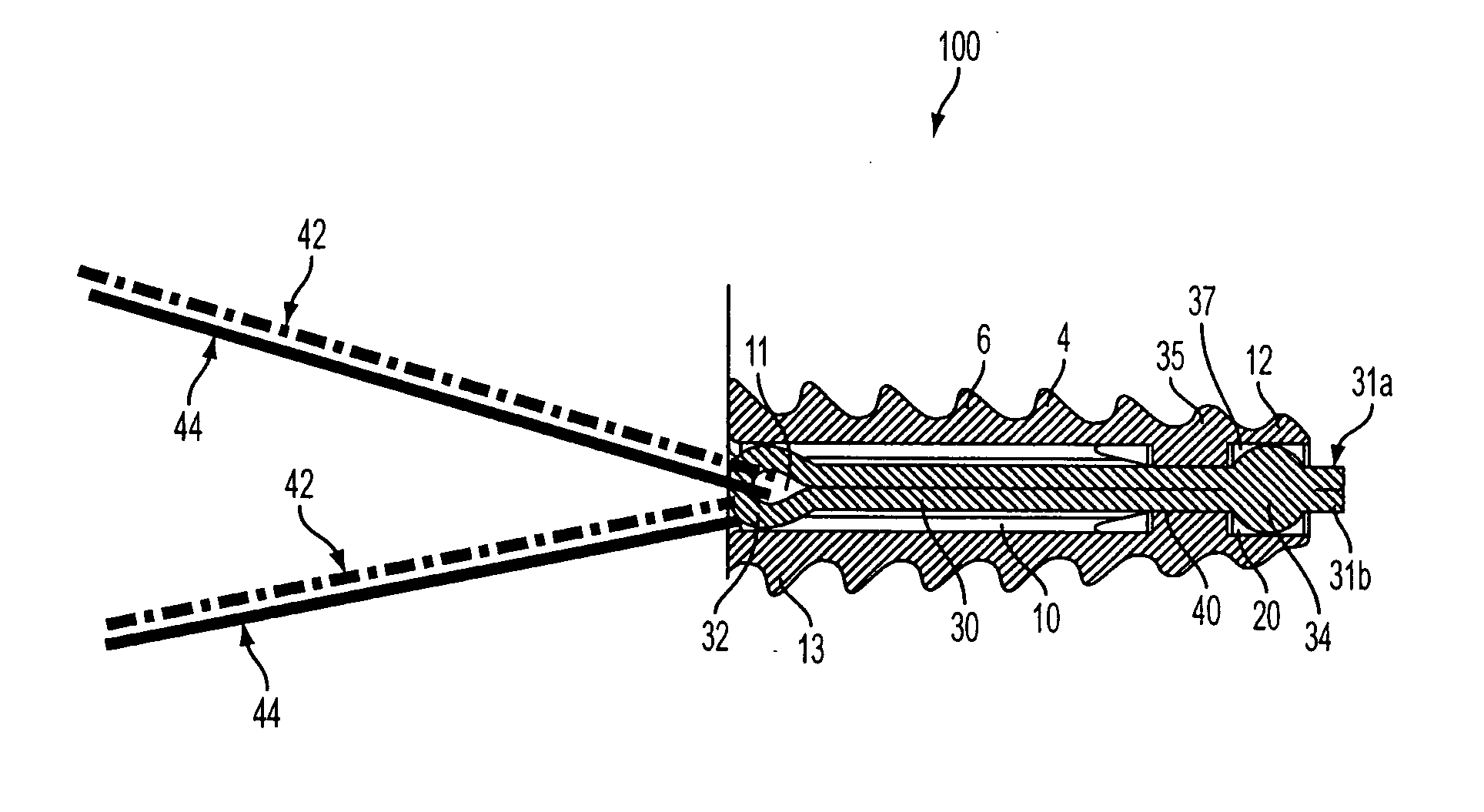
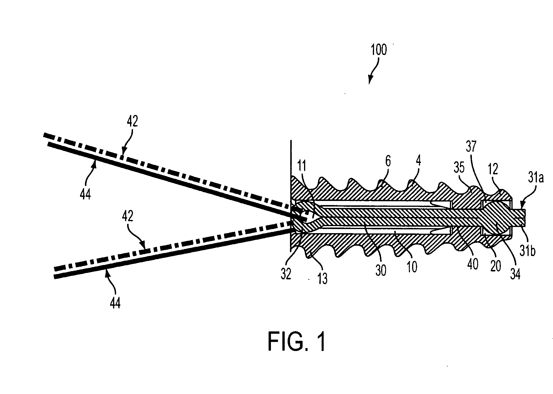
[0050] Referring now to the drawings, where like elements are designated by like reference numerals, FIGS. 1-6 illustrate a fully-threaded bioabsorbable suture anchor 100 of the present invention. The fully-threaded suture anchor 100 includes a body 4 provided in the shape of a tapered cylinder and having a distal end 12 and a proximal end 13.

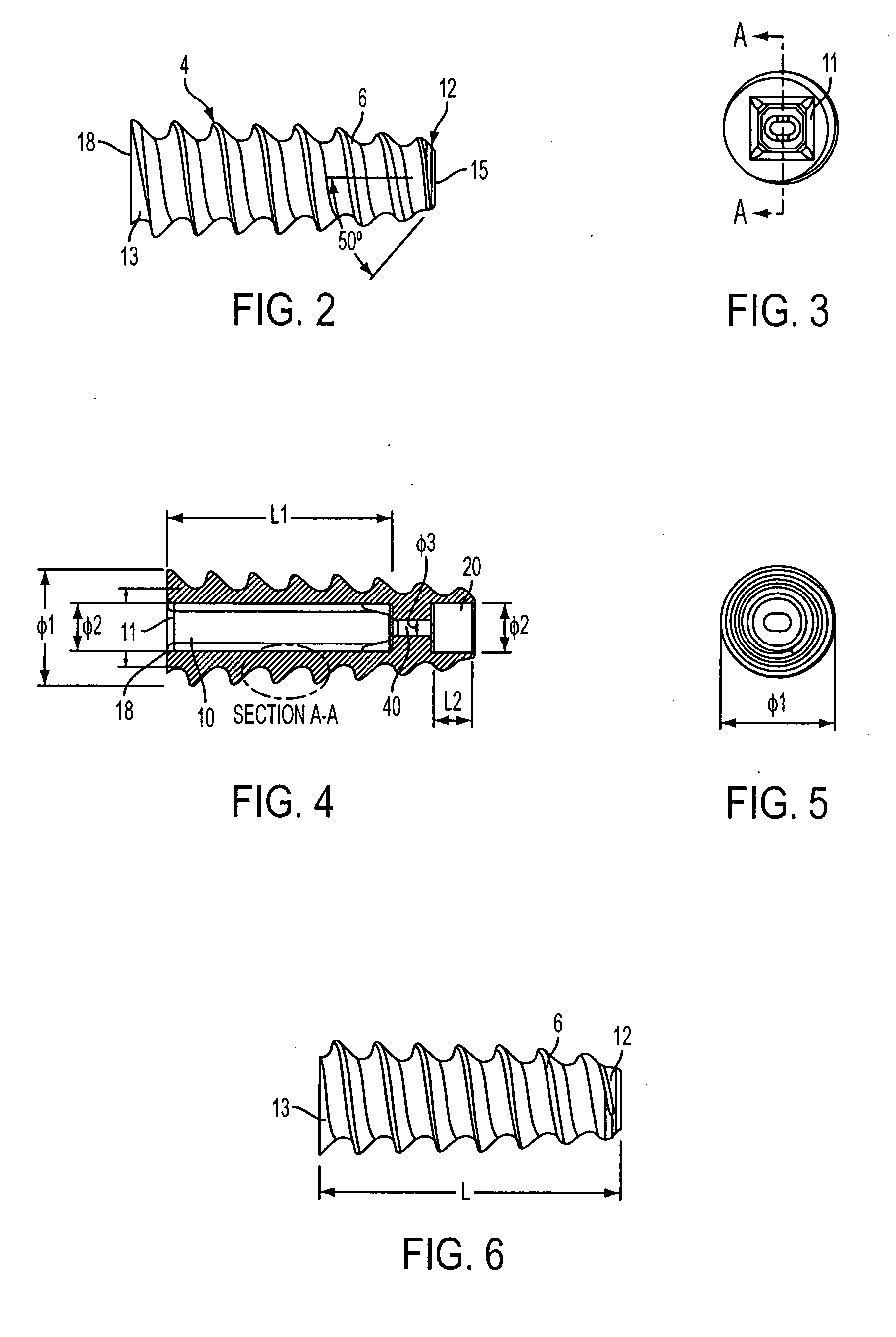
[0051] As shown in FIG. 1, the fully-threaded suture anchor 100 is provided with a continuous thread 6 which wraps around the body 4 in a clockwise direction, the crest of the threads tapering from wide to narrow from the proximal to the distal end of the anchor. The proximal threads of anchor 100 with the widest crest surfaces are designed to engage the thin cortical shell in osteopenic bone to prevent anchor “pull back,” which could cause the back of the anchor to be proud to the bone. In an exemplary embodiment, suture anchor 100 is provided with about eight thread flights wrapping around body 4, with the angle of the proximal surface of ea...


PUM

PropertyMeasurementUnit
diameteraaaaaaaaaa
angleaaaaaaaaaa
angleaaaaaaaaaa

Abstract

A suture anchor includes a threaded anchor body having a first central bore in communication with a second central bore. The suture anchor includes an internal eyelet formed of a loop disposed at least partially inside the first central bore. The ends extending from the loop are tied together to form at least one knot which is housed in the second central bore provided at the distal end of the anchor body. The knot increases the pullout strength of the suture even in soft bone, provides increased suture fixation, and eliminates the anchor “pull back.”

Description

FIELD OF THE INVENTION [0001] The present invention relates to an apparatus and method for anchoring surgical suture to bone. More specifically, the present invention relates to arthroscopic apparatus and methods for anchoring suture to bone using a fully-threaded bioabsorbable suture anchor having a loop inserted into the suture anchor. BACKGROUND OF THE INVENTION [0002] When soft tissue tears away from bone, reattachment becomes necessary. Various devices, including sutures alone, screws, staples, wedges, and plugs have been used in the prior art to secure soft tissue to bone. Recently, various types of threaded suture anchors have been developed for this purpose. Some threaded suture anchors are designed to be inserted into a pre-drilled hole. Other suture anchors are self-tapping. [0003] Problems can arise if the structure for attaching the suture fails, allowing the suture to become detached from the anchor. Also, the suture often is exposed to abrasion or cutting by sharp or r...

Claims


Application Information

Patent Timeline
Patent Type & Authority Applications(United States)
IPC IPC(8): A61B17/58
CPCA61B17/0401A61B2017/00004A61B2017/0409A61B2017/0458A61B2017/044A61B2017/0445A61B2017/0414A61B17/58A61B17/04A61B17/10A61L17/10A61L17/145
Inventor DREYFUSS, PETER J.
Owner ARTHREX
Why Eureka
Try Eureka