Device and method for reshaping mitral valve annulus

a technology of mitral valve and annulus, which is applied in the field of medical devices and methods, can solve the problems of affecting and many patients cannot withstand the trauma of open-heart surgery, so as to improve the coaption of mitral valve leaflets and reduce the distance

Inactive Publication Date: 2007-03-15
EDWARDS LIFESCIENCES CORP
View PDF14 Cites 260 Cited by
  • Summary
  • Abstract
  • Description
  • Claims
  • Application Information

AI Technical Summary

Benefits of technology

This patent describes a way to fix a damaged heart valve called a mital valve. It uses two different tools that can be applied separately to the valve's edges. One tool has a suction cup to hold the edge of the valve in place, and it also has something like a screw or staple to attach it securely to the wall of the heart. Then, after releasing the first part of the valve, the other tool comes along and does the same thing to the other side of the valve. Once both parts have been fixed, they pull tightly together which helps improve how well the valve works.

Problems solved by technology

The technical problem addressed in this patent text is the need for new methods to treat heart valve regurgitation in a minimally invasive way. Current surgical techniques are effective but traumatic for patients, and existing minimally invasive procedures have limitations in terms of the strength of the treatment and the anatomy of the heart. Therefore, there is a need for further approaches to treat heart valve regurgitation.

Method used


Image

  • Device and method for reshaping mitral valve annulus
  • Device and method for reshaping mitral valve annulus
  • Device and method for reshaping mitral valve annulus

Examples


Embodiment Construction

[0031] Various embodiments of the present invention depict medical implants and methods of use that are well-suited for treating mitral valve regurgitation. It should be appreciated that the principles and aspects of the embodiments disclosed and discussed herein are also applicable to other devices having different structures and functionalities. For example, certain structures and methods disclosed herein may also be applicable to the treatment of other heart valves or other body organs. Furthermore, certain embodiments may also be used in conjunction with other medical devices or other procedures not explicitly disclosed. However, the manner of adapting the embodiments described herein to various other devices and functionalities will become apparent to those of skill in the art in view of the description that follows.

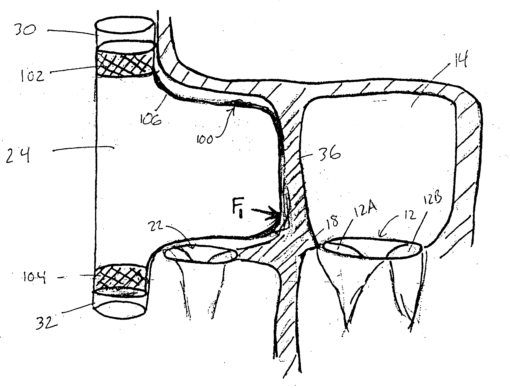
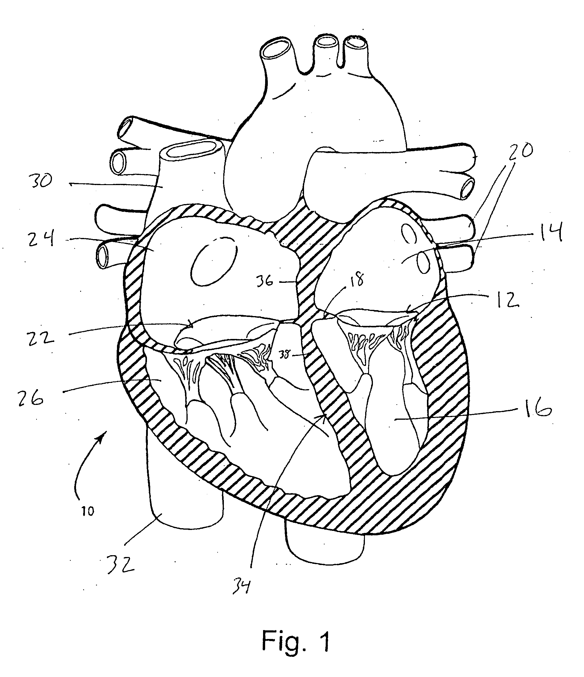
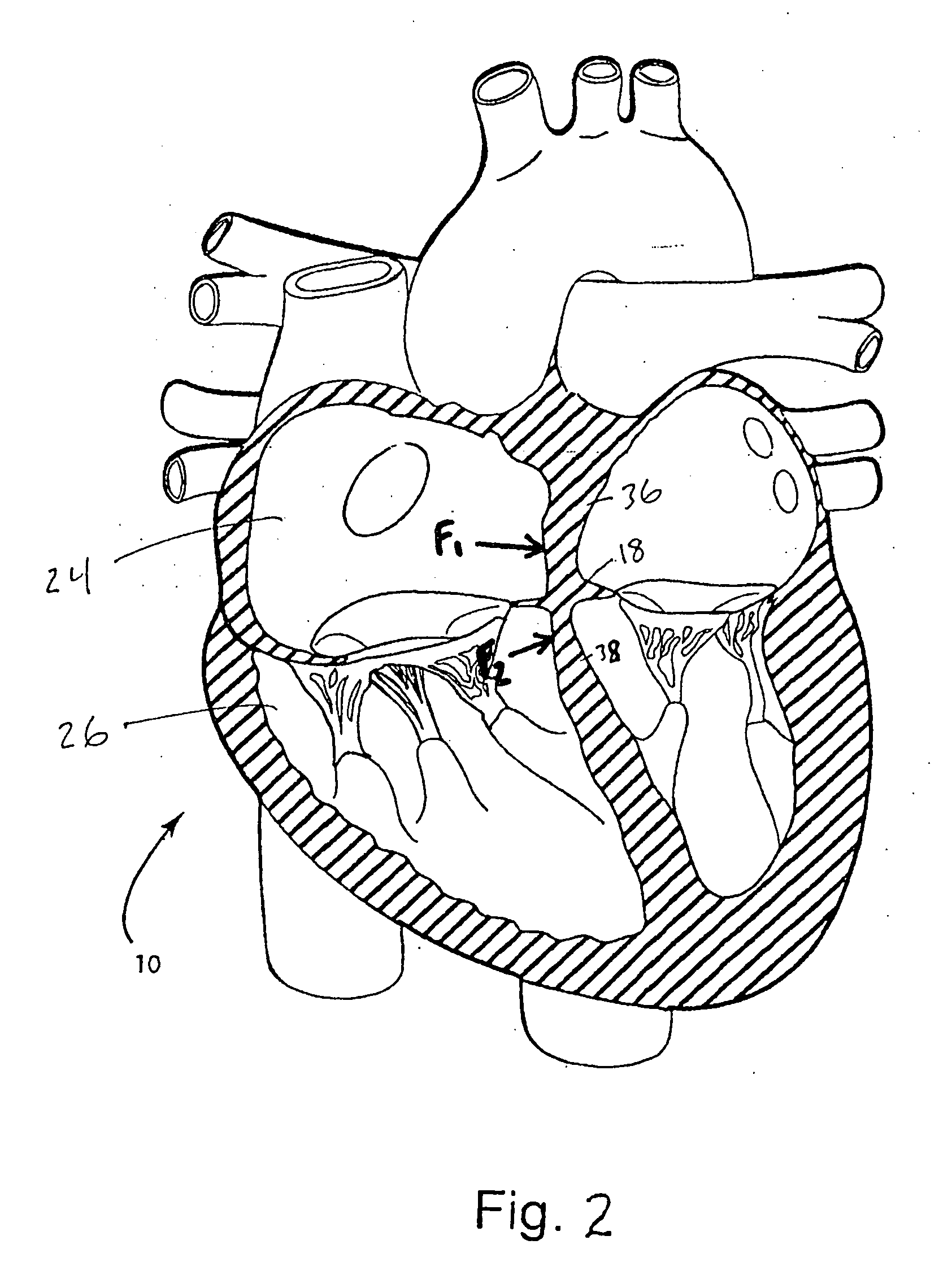
[0032] With reference now to FIG. 1, a four-chambered heart 10 is illustrated for background purposes. On the left side of the heart, the mitral valve 12 is locate...


PUM

PropertyMeasurementUnit
Forceaaaaaaaaaa

Abstract

Devices and methods for reshaping a mitral valve annulus are provided. One preferred device is configured for deployment in the right atrium and is shaped to apply a force along the atrial septum. The device causes the atrial septum to deform and push the anterior leaflet of the mitral valve in a posterior direction for reducing mitral valve regurgitation. Another preferred device is deployed in the left ventricular outflow tract at a location adjacent the aortic valve. The device is expandable for urging the anterior leaflet toward the posterior leaflet. Another preferred device comprises a tether configured to be attached to opposing regions of the mitral valve annulus.

Description


Claims


Application Information

Patent Timeline
Owner EDWARDS LIFESCIENCES CORP
Why Eureka
Try Eureka