Check patentability & draft patents in minutes with Patsnap Eureka AI!

Abnormality detection system, abnormality management apparatus, abnormality management method, probe and program

Active Publication Date: 2007-03-15
OKI ELECTRIC IND CO LTD
View PDF10 Cites 9 Cited by
  • Summary
  • Abstract
  • Description
  • Claims
  • Application Information

AI Technical Summary

Benefits of technology

[0010] An object of the present invention, which has been completed by addressing the problems of the abnormality detection in the related art, is to provide new and improved abnormality detection system, abnormality management apparatus, abnormality management method that enable accurate assessment of the scale of an abnormality having occurred in a network and thus enable prompt response to the abnormality by detecting the cause of the abnormality at an early stage, and also to provide a new and improved program executed for such abnormality management.
[0012] The present invention provides an abnormality detection system capable of accurately assessing the scale of an abnormality manifesting in a network based upon the abnormality levels indicated by probes dispersed in the network to monitor traffic in the network. Such an abnormality detection system assures network security by distinguishing a local abnormality occurring over a limited area in the network from an abnormality affecting the entire network and taking measures against for instance, abnormalities affecting the entire network.
[0023] In this case, the ratio of the number of parameters contained in the given ranges (reliable ranges) each set in correspondence to a specific parameter in relation to the parameter values at the other probes is calculated for each probe. Then, judgment can be accurately made as to whether abnormalities detected in the network are attributable to a single cause or different causes based upon the ratio of the number of parameters indicating values contained in the reliable ranges of the normal distribution to the total number of parameters.
[0029] As explained above, by adopting the present invention, the scale of an abnormality having occurred in a network can be accurately assessed and quick response to the abnormality is enabled as the cause of the abnormality is detected at an early stage. In addition, the abnormality detection processing is facilitated so as to reduce the processing load, the processing performance requirements and the processing cost.

Problems solved by technology

Trouble occurring in such a network includes problems caused by human interference such as a worm, as well as problems attributable to the network itself or problems occurring in electronic devices connected in the network.
For instance, if the information traffic on the Internet is analyzed through a standard sampling method, an erroneous detection is bound to occur frequently since the volume of data processed is constantly changing, and thus, the adoption of the standard sampling method in such an application is likely to prove problematic in practical use.
This necessitates an analysis of the payload portion of each packet containing data, which, in turn, is bound to significantly increase the load on the computer.
Furthermore, an illegal packet intended to cause a bug in the program executed to analyze the payload portion may induce an erroneous operation during abnormality detection processing.

Method used


Image

  • Abnormality detection system, abnormality management apparatus, abnormality management method, probe and program
  • Abnormality detection system, abnormality management apparatus, abnormality management method, probe and program
  • Abnormality detection system, abnormality management apparatus, abnormality management method, probe and program

Examples


first embodiment

(A) First Embodiment

Abnormality Detection System

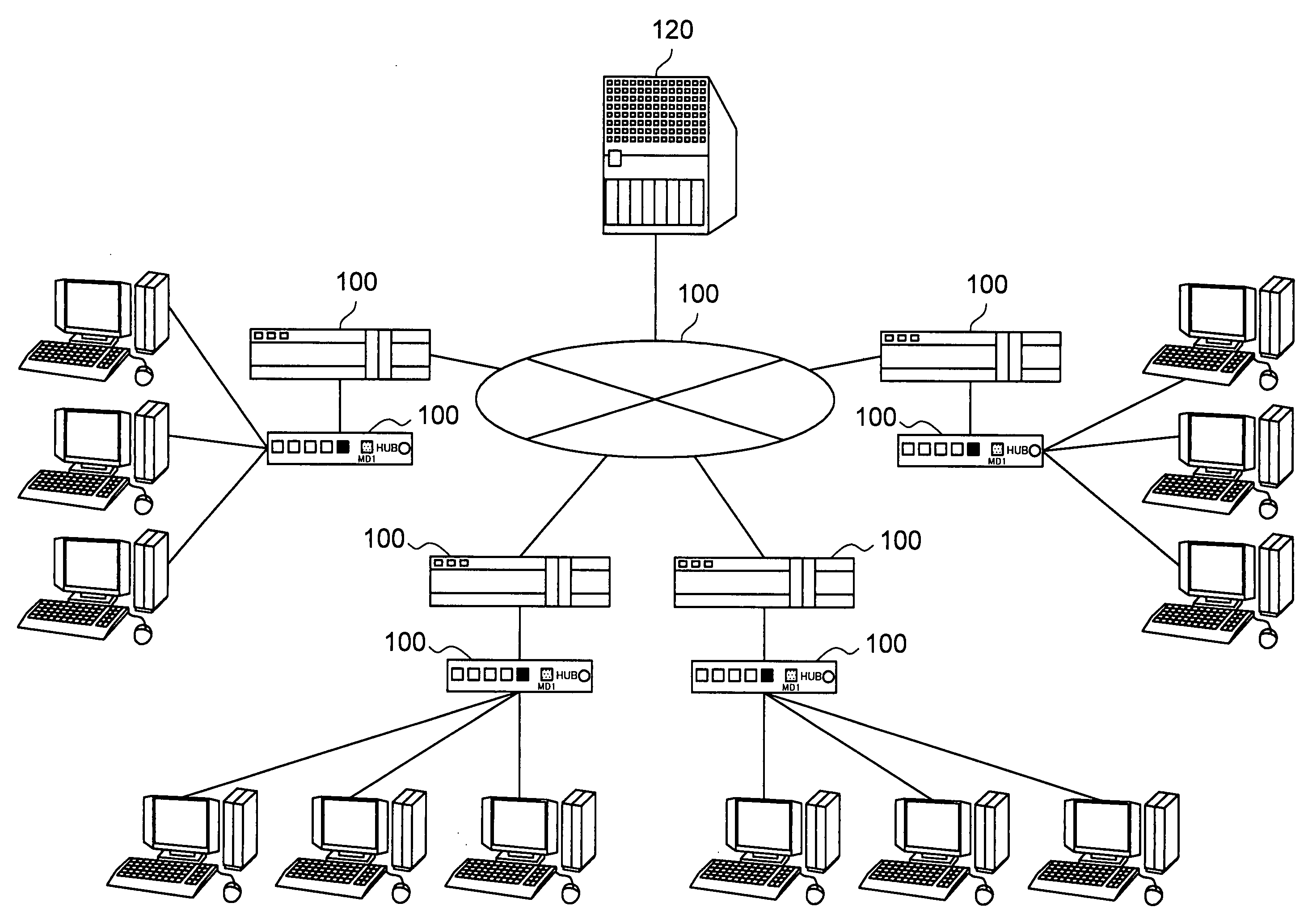
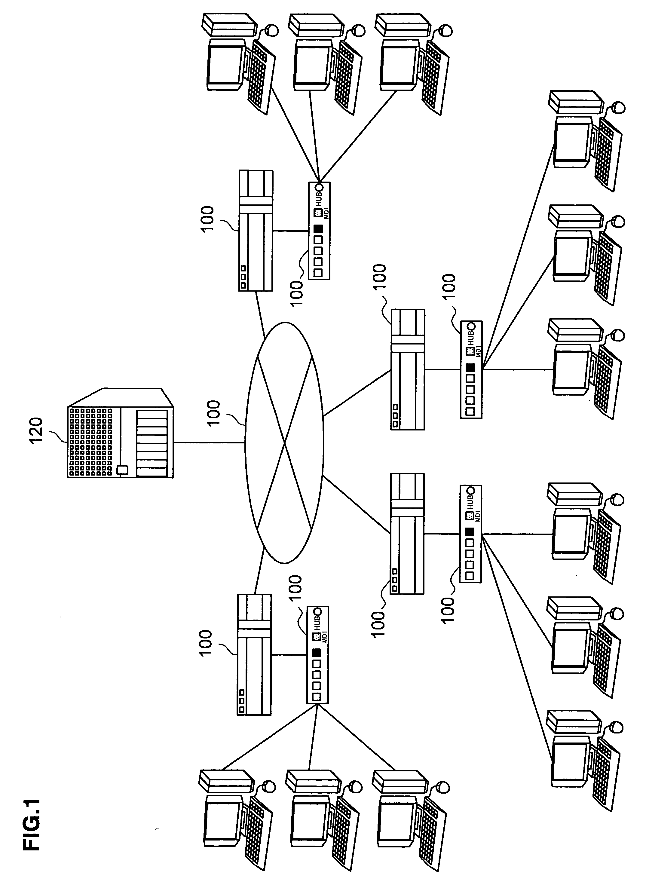
[0050]FIG. 1 is a block diagram schematically showing the structure adopted in the abnormality detection system. The abnormality detection system comprises a plurality of probes 110 disposed at arbitrary positions in a network 100 and an abnormality management apparatus 120 connected to the probes 110 via the network 100.

[0051] The network 100 is a communication network such as the Internet or a LAN, and may function as a communication path connecting the probes 110 to the abnormality management apparatus 120.

[0052] The term “probe” (110) is used to refer collectively to any network device connected to the network 100 and capable of monitoring packets transmitted on the network 100. Such probes 110 may each be disposed at a branching point in the network 100, e.g., at a router, a hub, a switch or the like. The probes 110 according to the present invention are not limited to the examples described above and a probe 110 may be constit...

second embodiment

(B) Second Embodiment

Probes 110

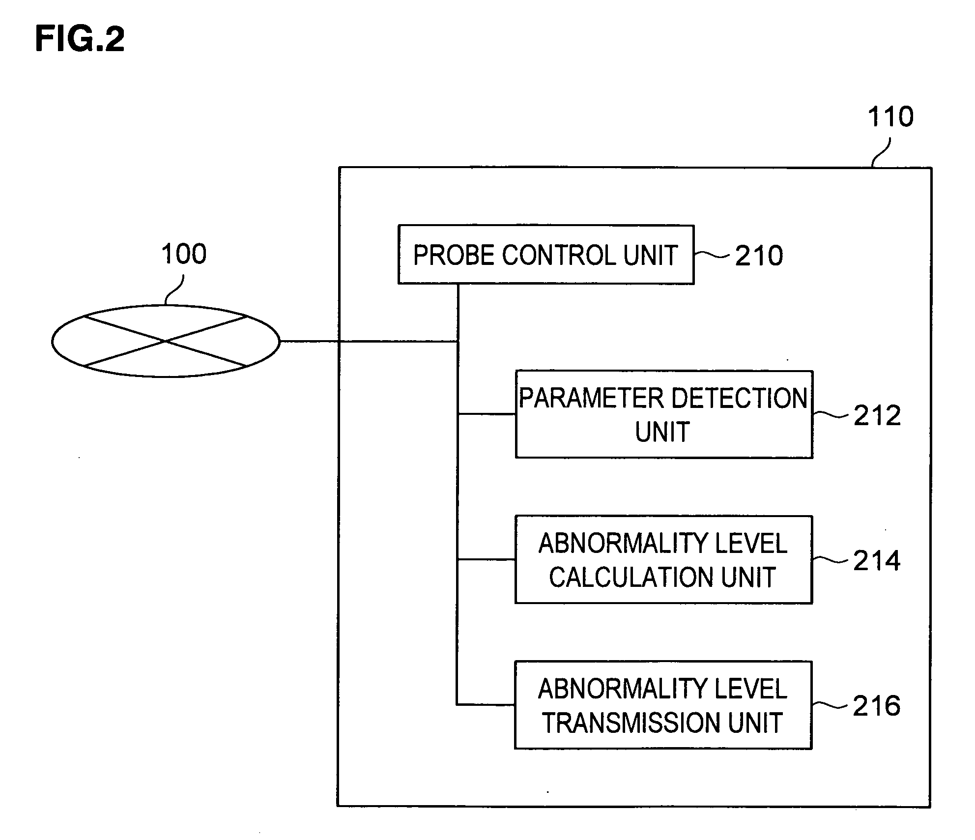
[0056]FIG. 2 is a block diagram schematically showing the structure adopted in the probes 110. The probes 110 each comprise a probe control unit 210, a parameter detection unit 212, an abnormality level calculation unit 214 and an abnormality level transmission unit 216.

[0057] The probe control unit 210, constituted with a semiconductor integrated circuit equipped with a central processing unit, manages and controls the entire probe 110.

[0058] The parameter detection unit 212 monitors the monitoring target, i.e., the traffic in the network 100 and detects the values of specific parameters related to the traffic.

[0059] The abnormality level calculation unit 214 calculates the level of abnormality based upon the parameter values detected by the parameter detection unit 212. The abnormality level may be calculated by adopting any of various existing methods such as calculating the sum of the parameter values detected by the parameter detection unit 212...

fourth embodiment

(D) Abnormality Management Apparatus

[0081]FIG. 6 is a block diagram schematically showing the structure adopted in an abnormality management apparatus 120 achieved in another embodiment. This abnormality management apparatus 120 comprises a management control unit 310, an abnormality level reception unit 312, an abnormality level storage unit 314, an abnormality analysis unit 316, a result output unit 318 and a cause analysis unit 350.

[0082] Since the functions of the management control unit 310, the abnormality level reception unit 312, the abnormality level storage unit 314, the abnormality analysis unit 316 and the result output unit 318 are substantially identical to those of the components in the third embodiment, a repeated explanation is not provided here and the following explanation focuses on the cause analysis unit 350 providing a new function.

[0083] The abnormality level reception unit 312 receives the values corresponding to a plurality of parameters related to the a...


PUM


Abstract

An abnormality management apparatus, connected via a network to a plurality of probes disposed at arbitrary positions in the network, comprises an abnormality level reception unit that receives information indicating an abnormality level calculated at each of the plurality of probes, an abnormality analysis unit that judges the scale of an abnormality manifesting in the network based upon an average value of the abnormality levels indicated at the plurality of probes and deviations relative to the average value and a result output unit that outputs results obtained at the abnormality analysis unit. The structure enables accurate assessment of the scale of an abnormality having occurred in the network and quick response to the abnormality by detecting its cause at an early stage.

Description

CROSS REFERENCE TO RELATED APPLICATION [0001] The disclosure of Japanese Patent Application No. JP 2005-262678 filed Sep. 9, 2005, entitled “Abnormality Detection System, Abnormality Management Apparatus, Abnormality Management Method, Probe and Program Executed for Abnormality Management”. The contents of that application are incorporated herein by reference in their entirety. BACKGROUND OF THE INVENTION [0002] 1. Field of the Invention [0003] The present invention relates to an abnormality detection system, an abnormality management apparatus, an abnormality management method, a probe and a program with which an abnormality occurring in a network is managed. [0004] 2. Description of the Related Art [0005] Today it is crucial to successfully avert trouble and disconnection in a network such as the Internet where an enormous volume of information is distributed in heavy transmission traffic. Trouble occurring in such a network includes problems caused by human interference such as a...

Claims


Application Information

Patent Timeline
IPC IPC(8): G06F11/00H04L12/70
CPCH04L1/24
Inventor NAKAMURA, NOBUYUKI
Owner OKI ELECTRIC IND CO LTD
Features
  • R&D
  • Intellectual Property
  • Life Sciences
  • Materials
  • Tech Scout
  • Unparalleled Data Quality
  • Higher Quality Content
  • 60% Fewer Hallucinations
Learn More