Balance shaft for a multicylinder in-line engine

a multi-cylinder, in-line engine technology, applied in the direction of machines/engines, mechanical equipment, vibration suppression adjustments, etc., can solve the problems of reducing the load-bearing capacity of the bearing position, deformation at high speed, and increasing the bearing stress, so as to achieve light design

a multi-cylinder, in-line engine technology, applied in the direction of machines/engines, mechanical equipment, vibration suppression adjustments, etc., can solve the problems of reducing the load-bearing capacity of the bearing position, deformation at high speed, and increasing the bearing stress, so as to achieve light design

US20070062329A1Active Publication Date: 2007-03-22DAIMLER AG

Image

  • Balance shaft for a multicylinder in-line engine
  • Balance shaft for a multicylinder in-line engine
  • Balance shaft for a multicylinder in-line engine

Examples


Embodiment Construction

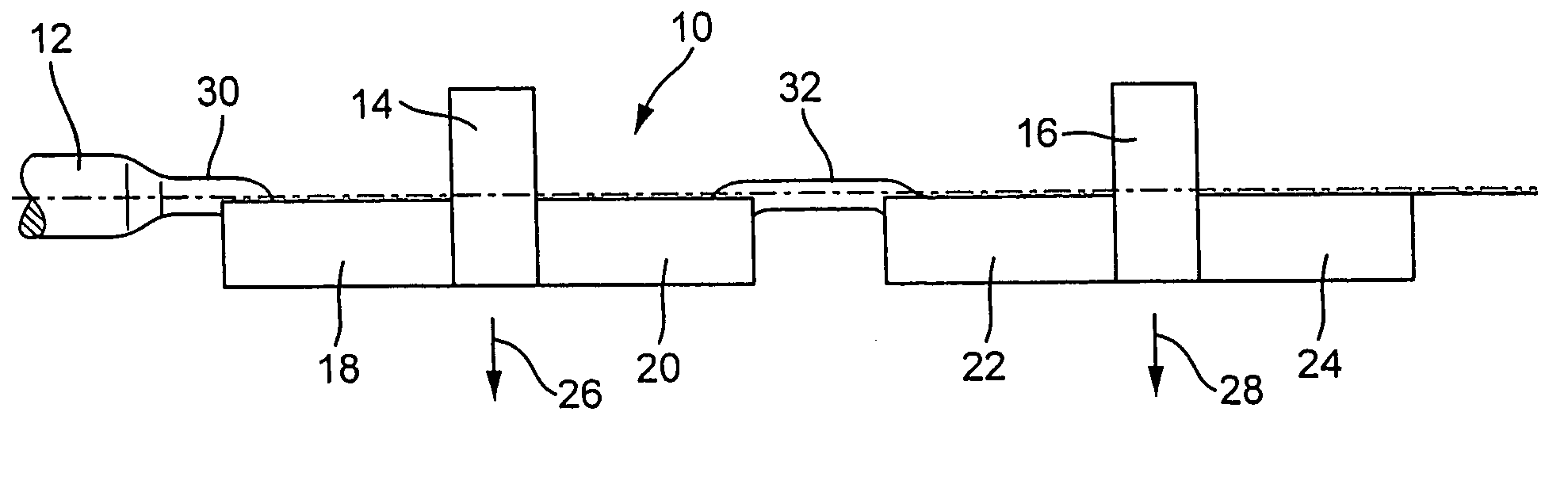
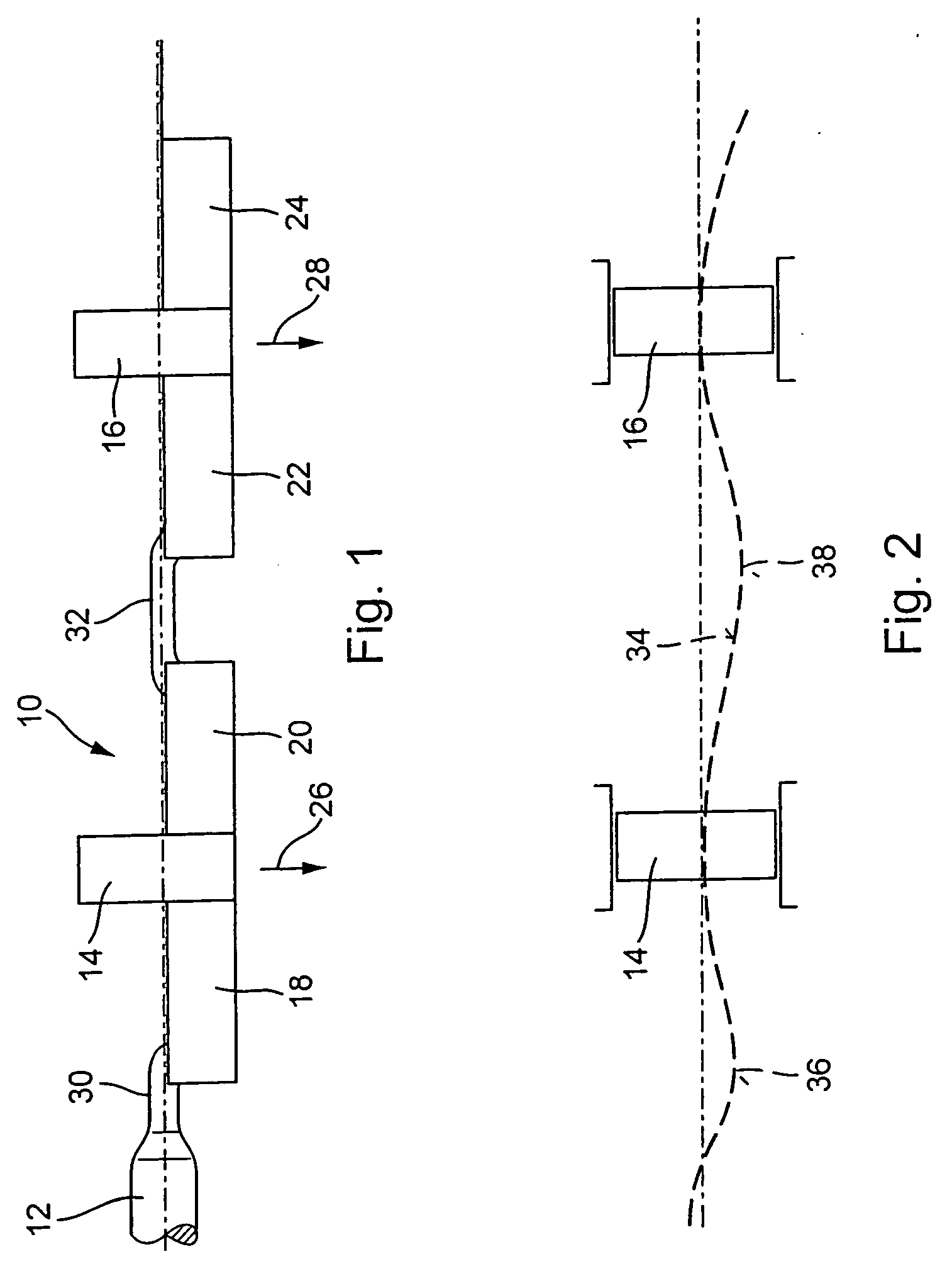
[0029] The balance shaft 10 shown in FIG. 1 is designed for a multi-cylinder, in-line engine and serves to balance second order mass forces. Normally, two balance shafts that counter-rotate at twice the engine speed are arranged offset relative to each other.

[0030] The balance shaft 10 is driven by a drive section 12, shown only as a section, with for example a sprocket wheel mounted on its end (not illustrated). The balance shaft 10 is provided with two bearing structures 14 and 16 at which the balance shaft 10 is rotatably supported, for example in an engine block. The bearing structures 14, 16 are cylindrical and have a circumference that is greater than a circumference of the other sections of the balance shaft 10. In this way, the balance shaft 10 can be slid from one end into the bearings of the engine block. A center axis of the balance shaft 10 is indicated by a broken line.

[0031] The balance shaft 10 has a total of four imbalance weight sections 18, 20, 22 and 24, with tw...


PUM


Abstract

In a balance shaft for a multi-cylinder in-line engine with at least two imbalance weight sections and at least one bearing structure wherein the balance shaft has imbalance weight sections being arranged symmetrically relative to the bearing position and at least one of the imbalance weight sections is connected to a further shaft section at an end facing away from the bearing position, a flexible coupling element that enables a deflection of the end of the connected imbalance weight section in the direction of the resulting centrifugal forces when the balance shaft rotates is provided between the end of the at least one imbalance weight section facing away from the bearing position and the further shaft section.

Description

[0001] This is a Continuation-In-Part Application of International application PCT / EP2005 / 002662 filed Mar. 12, 2005 and claiming the priority of German application 10 2004 014 014.6 filed Mar. 23, 2004.BACKGROUND OF THE INVENTION [0002] The invention relates to a balance shaft for a multi-cylinder, in-line engine with at least two imbalance weight sections and at least one bearing structure, with the imbalance weight sections being arranged symmetrically relative to the bearing structure and at least one of the imbalance weight sections being connected to a further shaft section at an end facing away from the bearing structure. [0003] From German patent application DE 199 47 271 C1, a balance shaft for a multi-cylinder in-line engine is known that has two imbalance weight sections. The two imbalance weight sections are symmetrically arranged on either side of a central bearing structure. Two further bearing structure are each arranged to the right and left of the imbalance weight s...

Claims


Application Information

Patent Timeline
22 Mar 2007
Publication
US20070062329A1
IPC
F02B75/06; F16C11/00; F16F15/26
CPC
F02B75/06; Y10T74/2184; F16F15/264; F16C3/18
Inventors
HOFHEINZ, WERNER; JUTZ, BERNHARD