Needle bar driving system for sewing machines

a driving system and needle bar technology, applied in the field of needle bar driving system, can solve the problems of affecting the operation of the machine, generating high noise, and strong vibration of the machine housing, and achieving the effects of reducing noise, increasing accuracy, and improving speed operation

Active Publication Date: 2015-09-08
INTELLIQUILTER
View PDF4 Cites 2 Cited by
  • Summary
  • Abstract
  • Description
  • Claims
  • Application Information

AI Technical Summary

Benefits of technology

[0006]There is a long-existing need to a better-balanced needle bar driving system, which if can be created, can reduce noise, increase accuracy, enables higher speed operation and last, but not least enables a lighter design for the whole sewing machine. The object of the invention is to provide such a needle bar driving system.SUMMARY OF THE INVENTION
[0012]In this embodiment the guided movement of the counterweight piston is provided by a guiding cylinder, and the cylinder and the counterweight piston are made of materials of differing hardness for providing smooth sliding movement of the counterweight piston in the cylinder.

Problems solved by technology

In high speed sewing machines, such non-compensated inertia forces cause strong vibrations of the machine housing adversely affecting the operation.
These vibrations generate high noise.
Several designs like U.S. Pat. Nos. 4,539,922 and 3,040,682 have been suggested to eliminate or decrease the problems outlined above, however, these solutions have proven either less efficient in decreasing vibration, or too complex and expensive in design.
While they decreased one or more components of the vibration, they have also caused a further source of unbalance.
The problems get more acute when there is a need for high speed operation with increased accuracy.

Method used


Image

  • Needle bar driving system for sewing machines
  • Needle bar driving system for sewing machines
  • Needle bar driving system for sewing machines

Examples


Embodiment Construction

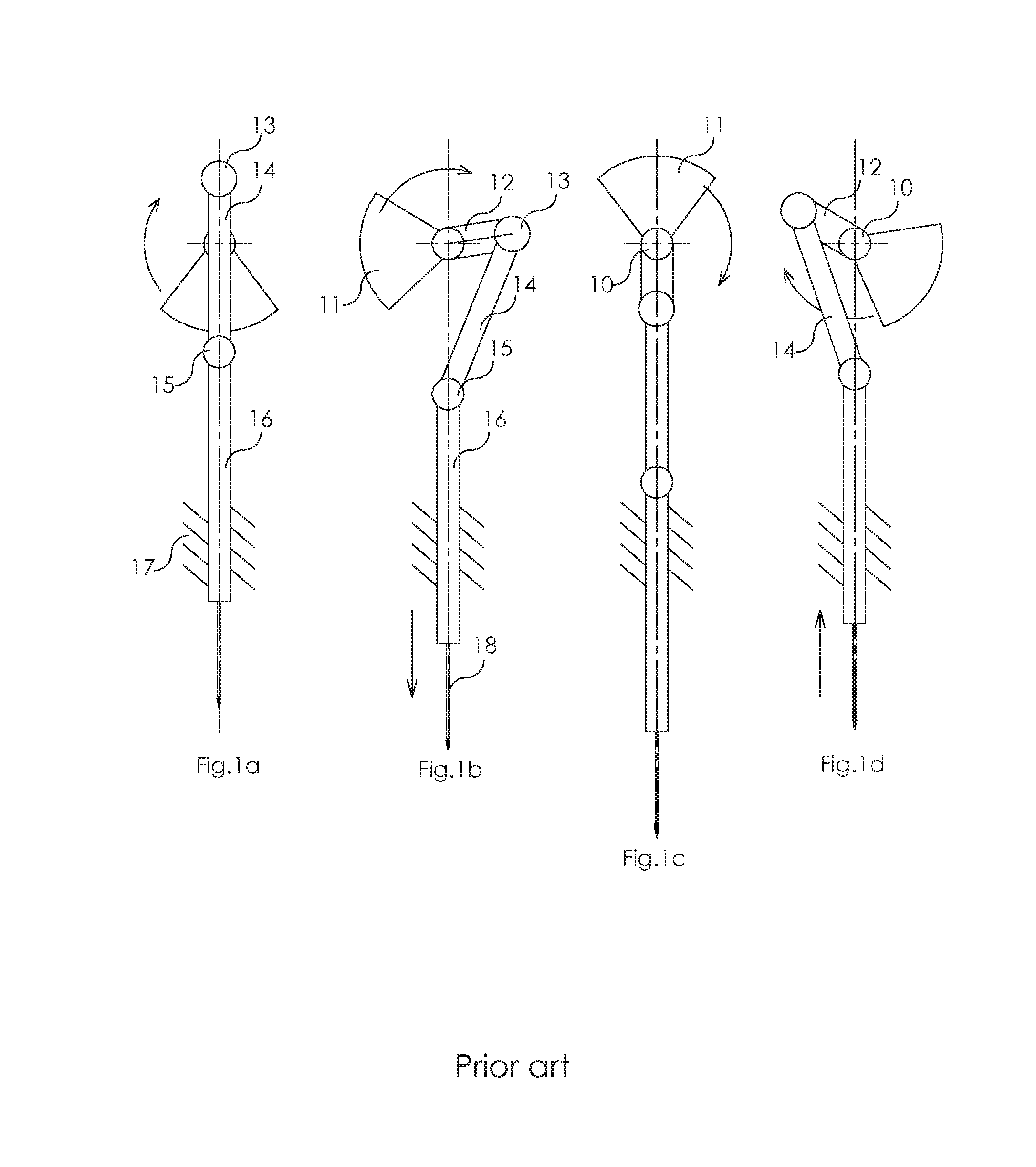
[0020]Reference is made to FIGS. 1a to 1d showing only the most important parts of a prior art needle bar (and needle) driving system. An armshaft 10 is rotated in the direction of the arrows with a constant speed, and the phase drawings 1a to 1d show the assembly in positions being in respective around 90° degrees offset to each other. The assembly can be seen best in sketch FIG. 1b, wherein the armshaft 10 is permanently connected with an asymmetric counterweight 11, where the central point of the mass is offset by a predetermined distance from the axis of the armshaft. Just in diagonally opposite direction from the line section connecting this central point and the axis, and in the extension thereof a crankshaft 12 is also firmly attached to the armshaft 10 having a pivot pin 13 at the remote end thereof. A first end of a link bar 14 is connected to the pivot pin 13 so that the crankshaft 12 and the link bar 14 can take any angular position relative to each other. The second (rem...


PUM


Abstract

Improved needle bar driving system for sewing machines, that comprises an armshaft rotating with a predetermined speed; a needle bar driving assembly driven by the armshaft and has a needle bar that performs a reciprocating guided linear movement along a substantially vertical axis; a counterweight driving assembly is driven by the armshaft; and a counterweight piston driven by the counterweight driving assembly, and the counterweight piston also performs a reciprocating linear guided movement along an axis parallel to the axis, wherein the movements of the counterweight driving assembly and of the counterweight piston are always opposite to the movement of the needle bar driving assembly and of the needle bar, wherein the combined torque of the counterweight piston and the counterweight driving assembly acting on the armshaft is substantially equal to the combined torque of the needle bar and needle bar driving assembly acting also on the armshaft, but the two torques have opposite direction, whereby the armshaft gets substantially balanced.

Description

FIELD OF THE INVENTION[0001]The invention relates to sewing machines and more particularly to an improved needle bar driving system with decreased vibration and better balance.DESCRIPTION OF THE PRIOR ART[0002]In conventional sewing machines designed as suggested by U.S. Pat. No. 2,128,120 having their needle bar drive designed as a crank drive, a counterbalance weight firmly secured to the armshaft of the machine is provided rotating in opposition to the crankpin. The counterweight is selected to equilibrate the rotating masses, namely the crank arm with the crank pin and a portion of the needle bar link, and partly the vertical first order inertia forces which are caused by the needle and a portion of the needle bar link. This partial compensation, however, is a compromise justifiable only for low-speed to medium speed sewing machines, since along with a partial compensation for the vertical inertia forces, a horizontal component develops, so that a rotary inertia force vector is ...

Claims


Application Information

Patent Timeline
Patent Type & Authority Patents(United States)
IPC IPC(8): D05B69/00D05B55/14
CPCD05B55/14D05B11/00
Inventor KASA, ZOLTANLORINCZ, LASZLO ISTVANHORVATH, JANOS
Owner INTELLIQUILTER
Why Eureka
Try Eureka