Method for manufacturing a flexible display

a flexible display and manufacturing method technology, applied in the direction of identification means, instruments, signs, etc., can solve the problems of large amount of adhesive material for the entire coating of adhesive material over the supporting substrate, affecting the yield of devices formed over the flexible substrate, and the inability to control the debonding effect well

Inactive Publication Date: 2007-03-22
IND TECH RES INST
View PDF5 Cites 40 Cited by
  • Summary
  • Abstract
  • Description
  • Claims
  • Application Information

AI Technical Summary

Benefits of technology

[0007] Accordingly, at least one objective of the present invention is to provide a method for supporting a flexible substrate on a supporting substrate capable of preventing generation of bubbles in the adhesive material layer between the supporting and the flexible substrates.
[0008] At least another objective of the present invention is to provide a method for manufacturing a flexible display. By using the method of the present invention, after the devices are formed on the flexible substrate, the flexible substrate can be easily taken off from the supporting substrate without residual adhesive material on the flexible substrate.
[0029] In the present invention, since the plurality of adhesive substances between the supporting substrate and the flexible substrate is located in a discrete arrangement, the adhesive substances not only provide a better adhesive effect, but also are easier removal of flexible substrate from the supporting one. Therefore, the problem that the adhesive material, which is entirely coating over the supporting substrate, remains on the flexible substrate can be overcome. The design of the discrete arrangement provides channels for the air bubbles generated in the adhesive material to escape and prevents the permeation of solutions during the wet processes.

Problems solved by technology

However, the result that the flexible substrate attaches onto the supporting substrate will affect the yield of the devices formed over the flexible substrates.
Among the aforementioned methods, entirely coating of the adhesive material over the supporting substrate needs large amount of adhesive material.
Moreover, although entirely coating of the adhesive material over the supporting substrate can increase the adhesion between the flexible substrate and the supporting substrate, the de-bonding result cannot be well controlled by modifying the contact area between the flexible substrate and the supporting one while the flexible substrate is taken off from the supporting substrate.
However, the cost of the research development is relatively high.
Nevertheless, the cost of the equipment used in the vacuum attachment is high and the air bubbles between the substrates are not easily removed under the vacuum environment.
Furthermore, the displacement between the flexible and supporting substrates might easily occur.
In addition, the de-bond of the flexible substrate performed by releasing the vacuum condition or using the assistant tools might result in apparent stress variation.
Moreover, the lack of adhesive material between the flexible and supporting substrates might also cause the deformation of the supporting substrate without releasing the stress generated in the thermal process.
Further, it is necessary to develop a new device for holding the supporting and the flexible substrates without adhesive and vacuum attachment so that the cost is high.
Also, there are many limitations on using the carrier to carry the supporting substrate in the present equipments.

Method used


Image

  • Method for manufacturing a flexible display
  • Method for manufacturing a flexible display
  • Method for manufacturing a flexible display

Examples


Embodiment Construction

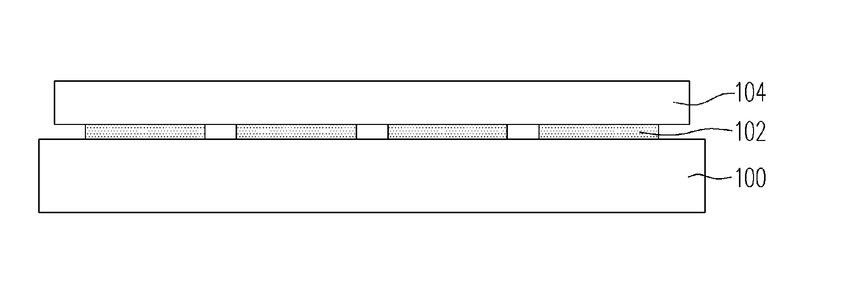
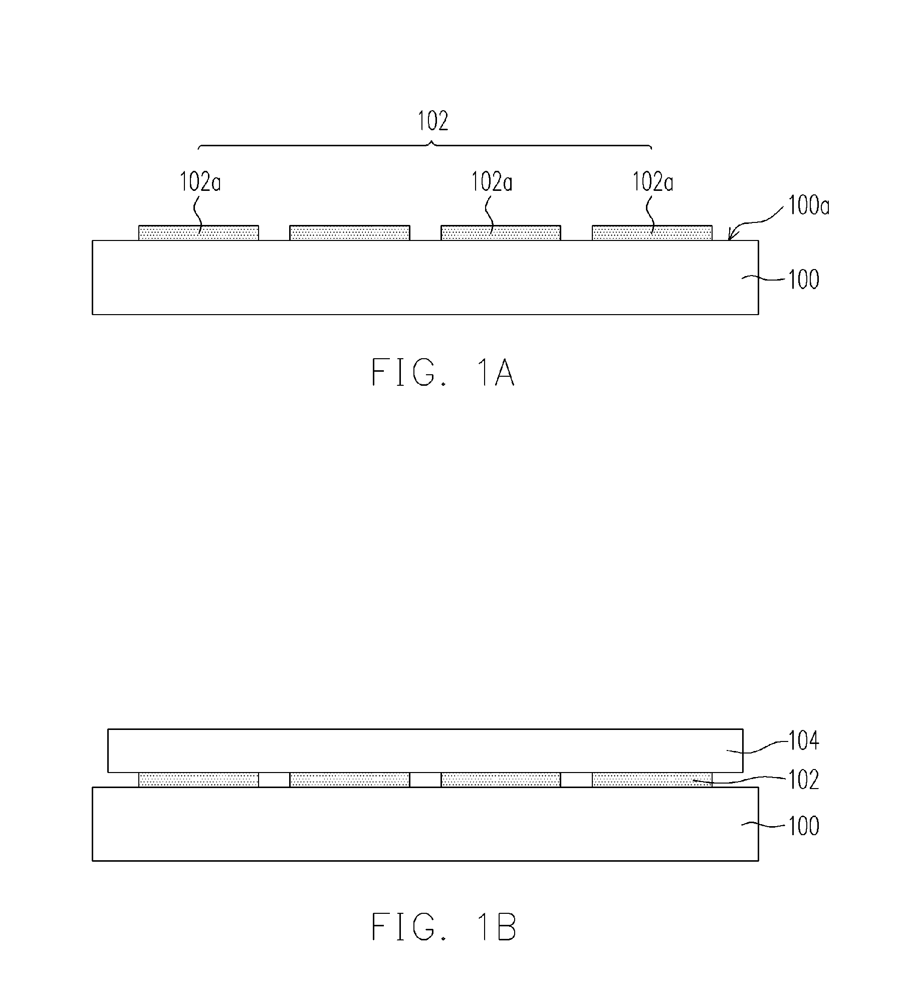
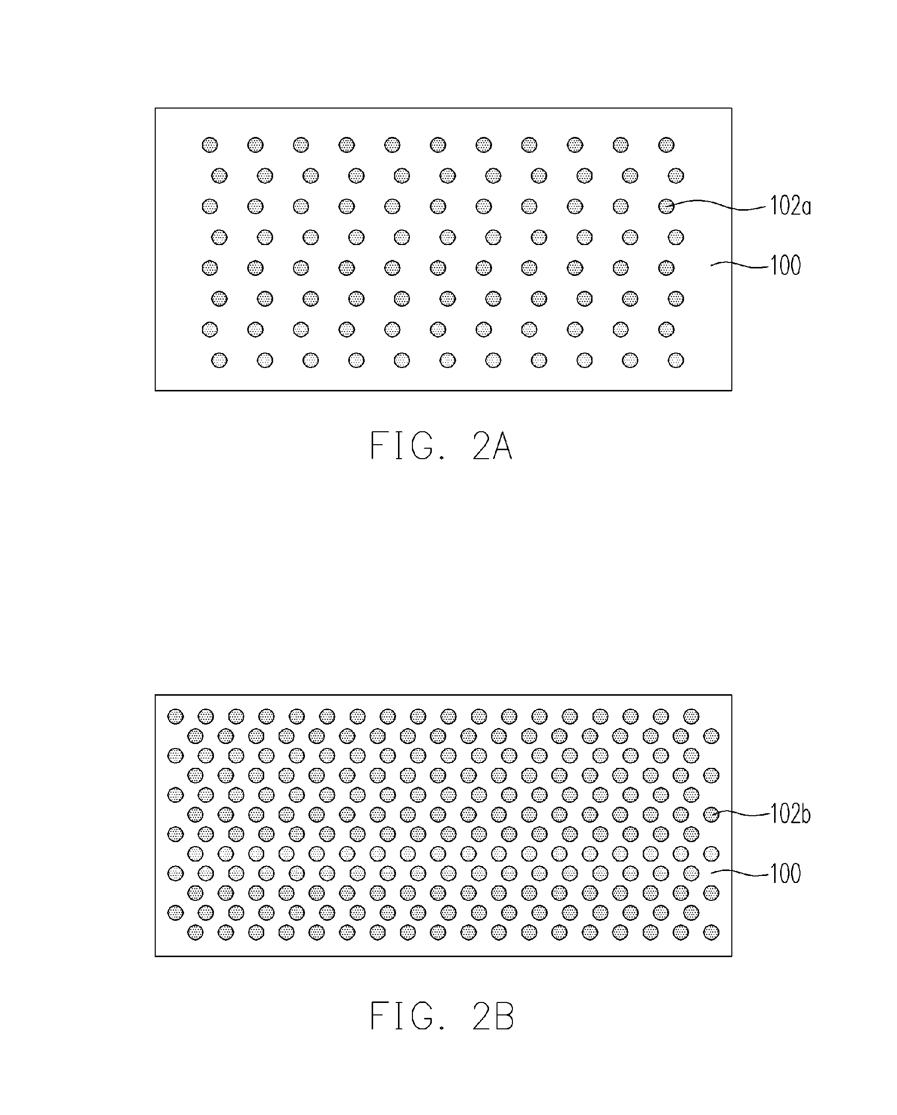
[0035]FIGS. 1A through 1B are cross-sectional views illustrating a method for supporting a flexible substrate according to a preferred embodiment of the invention. As shown in FIG. 1A, a supporting substrate 100 is provided. The supporting substrate 100 is disposed on a carrier (not shown) and the material of the supporting substrate 100 includes, for example but not limited to, refractory material. Preferably, the material of the supporting substrate 100 is plastic or glass. Thereafter, an adhesive material layer 102 is formed on a surface of the supporting substrate 100. The adhesive material layer 102 is composed of several adhesive substances 102a. The adhesive substances 102a are located on the supporting substrate 100 in a discrete arrangement. FIGS. 2A through 2E are schemas showing various arrangements of the adhesive substances according to one preferred embodiment of the invention. As shown in FIGS. 2A, 2B, 2C, 2D and 2E, the aforementioned discrete arrangement can be, for...


PUM

PropertyMeasurementUnit
flexibleaaaaaaaaaa
adhesiveaaaaaaaaaa
refractoryaaaaaaaaaa

Abstract

The invention is directed to a method for supporting a flexible substrate. The method comprises steps of providing a supporting substrate and then forming an adhesive material layer on a surface of the supporting substrate, wherein the adhesive material layer is composed of a plurality of adhesive substances and the adhesive substances are located on the supporting substrate in a discrete arrangement. A flexible substrate is disposed on the supporting substrate, wherein the flexible substrate is attached onto the supporting substrate through the adhesive substances.

Description

CROSS-REFERENCE TO RELATED APPLICATION [0001] This application claims the priority benefit of Taiwan application Serial no. 94132412, filed on Sep. 20, 2005. All disclosure of the Taiwan application is incorporated herein by reference. BACKGROUND OF THE INVENTION [0002] 1. Field of Invention [0003] The present invention relates to a method for manufacturing an electronic device. More particularly, the present invention relates to a method for manufacturing a flexible display. [0004] 2. Description of Related Art [0005] In the process for manufacturing a display, the current development trend is towards the use of the flexible substrate instead of the use of the glass substrate. In order to solve the problem due to the use of the flexible substrate in the manufacturing process, not only the manufacturing equipments need to be re-designed to be compatible with the flexible substrate but also the flexible substrate need to be supported by using the supporting substrate to be compatible...

Claims


Application Information

Patent Timeline
Patent Type & Authority Applications(United States)
IPC IPC(8): B32B7/14
CPCB32B37/1292G02F1/133305G09F3/10G09F7/12H01L51/0097Y10T156/1189H05K3/007H05K3/386H05K2203/016H05K2203/0522H05K1/0393H10K77/111
Inventor CHANG, KU-HSIENLIAO, CHI-CHANGWANG, HSING-LUNG
Owner IND TECH RES INST
Why Eureka
Try Eureka