Operating device for on-vehicle equipment

Active Publication Date: 2007-03-22
HITACHI ASTEMO LTD
View PDF3 Cites 74 Cited by
  • Summary
  • Abstract
  • Description
  • Claims
  • Application Information

AI Technical Summary

Benefits of technology

[0021] According to the present invention, safety can be assu

Problems solved by technology

Therefore, it is not favorable from the viewpoint of careful driving.
Therefore, it is not favorable from the viewp

Method used


Image

  • Operating device for on-vehicle equipment
  • Operating device for on-vehicle equipment
  • Operating device for on-vehicle equipment

Examples


Example

First Embodiment

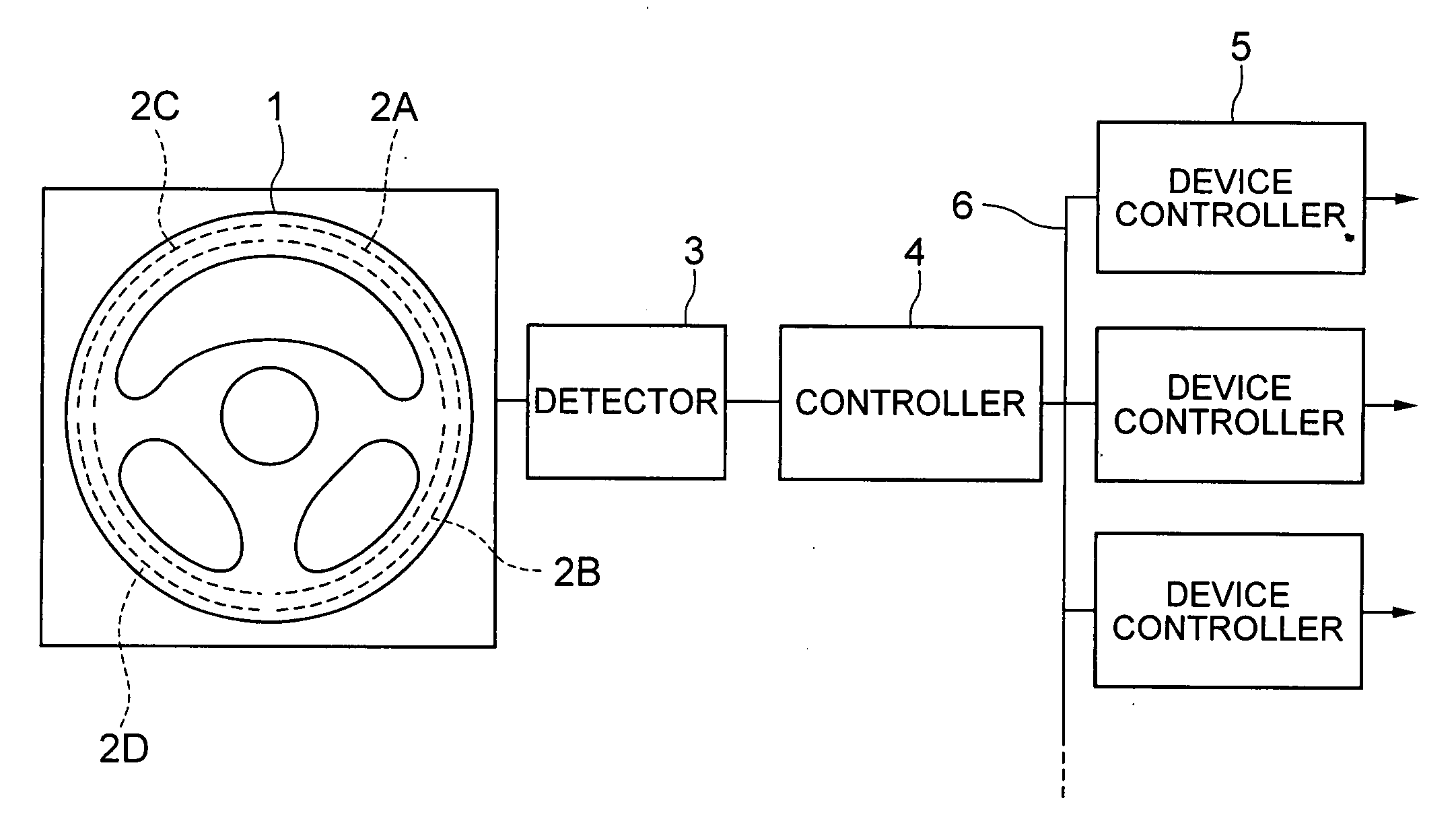
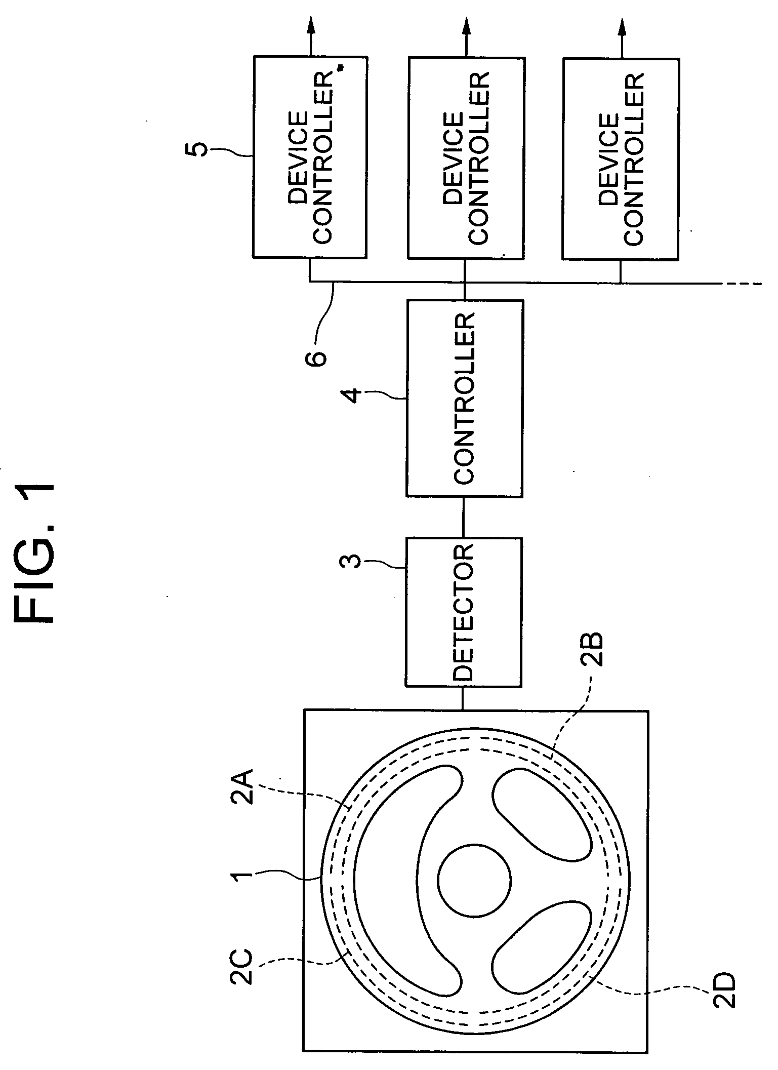
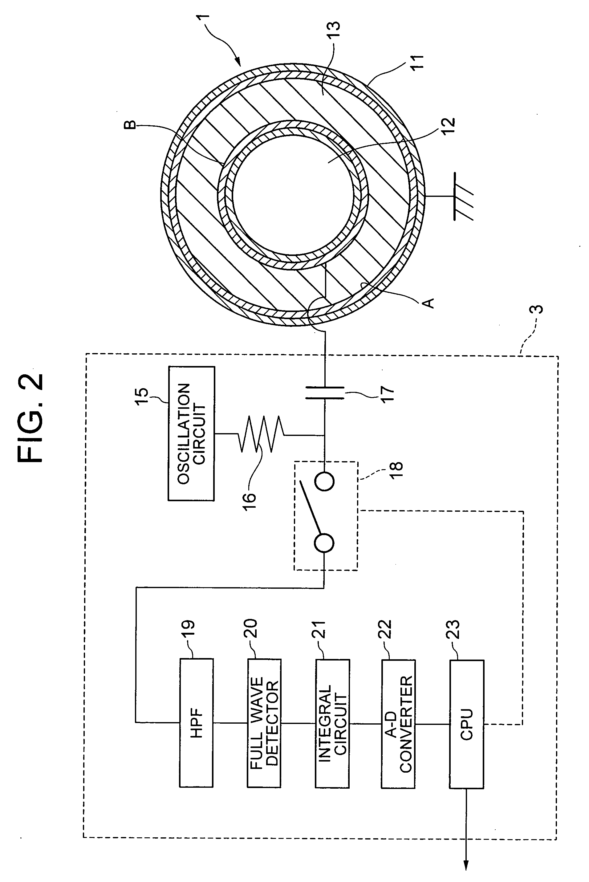
[0044]FIG. 1 is a general configuration diagram of a first embodiment of an operating device for on-vehicle equipment according to the present invention. FIG. 2 shows a configuration of a force sensor and a detector in the present embodiment. In the operating device for on-vehicle equipment in the present embodiment, a plurality of (in the illustrated example, four) force sensors 2 (2A to 2D) are buried in a grasping part of a steering wheel 1 used as a vehicle steering tool, as shown in FIG. 1. Outputs of respective force sensors 2 are input to a detector 3. The detector 3 detects force acted on the grasping part on the basis of the outputs of respective force sensors 2, and outputs the detected force to a controller 4. The controller 4 makes a decision whether the input detected signal is a signal for operating a plurality of (in the illustrated example, three) device controllers 5 for on-vehicle equipment. Based on the decision, the controller 4 outputs an operat...

Example

Second Embodiment

[0065]FIG. 9 shows an operation block diagram of a second embodiment obtained by applying the operating device in the first embodiment to channel selection and volume control of an audio device installed on an automobile. In the present second embodiment, functions associated with operations of the audio device are set for the force sensors 2A to 2D shown in FIG. 1. In other words, if the driver grasps a steering wheel part associated with the force sensor 2C located on the left-top side of the steering wheel shown in FIG. 1 only once, then operation of the force sensor 2C is detected by the detector 3 shown in FIG. 1. It is judged by the controller 4 to be a specific operating signal for a preset audio device. In the present second embodiment, it is judged to be a control mode for the audio device. After it is judged to be the control mode, the force sensor 2A and the force sensor 2B located on the right hand side of the steering wheel 1 shown in FIG. 1 are recogn...

Example

Third Embodiment

[0069]FIG. 10 shows an operation block diagram of a third embodiment obtained by applying the operating device in the first embodiment to power window opening and closing operation on an automobile. In the present third embodiment, functions associated with operations of the power window are set for the force sensors 2A to 2D shown in FIG. 1. In other words, the driver strongly grasps a region associated with the force sensor 2A or the force sensor 2B located on the right-hand side of the steering wheel 1 shown in FIG. 1 or a region associated with the force sensor 2C or the force sensor 2D located on the left-hand side of the steering wheel 1 for at least a preset time period. As a result, the controller 4 recognizes it as a power window operation. And changeover to a power window control mode preset so as to be associated with a force sensor 2 to which an operating signal has been input is conducted. For example, if a first operation is conducted by using the forc...


PUM


Abstract

An operating device capable of assuring safety when operating on-vehicle equipment of an automobile is implemented. The operating device includes force sensors buried in a grasping part of a steering wheel in a vehicle, a detector for detecting force acted on the grasping part on the basis of an output signal of each of the force sensors, and a controller for outputting an operating signal to a piece of the on-vehicle equipment mounted on the vehicle on the basis of a detected signal supplied from the detector. As a result, it is possible to operate force sensors and operate the on-vehicle equipment by adjusting force used to grip the steering wheel or pressing the steering wheel without letting go the driver's hold of the steering wheel.

Description

INCORPORATION BY REFERENCE [0001] The present application claims priority from Japanese application JP2005-266619 filed on Sep. 14, 2005, the content of which is hereby incorporated by reference into this application. BACKGROUND OF THE INVENTION [0002] The present invention relates to an operating device for operating on-vehicle equipment such as on-automobile equipment. In particular, the present invention relates to an operating device having operating switches provided in a steering part, such as a steering wheel. [0003] As for on-vehicle equipment such as on-automobile equipment, on-vehicle devices such as an audio device, a car navigation device, and an information terminal can be mentioned besides accessory devices such as a brake, an accelerator or a power window. Typically, foot-depressed pedals are used in operating devices such as the brake and accelerator. In operating devices for on-vehicle devices, operating switches and hand screws such as knobs attached to respective ...

Claims


Application Information

Patent Timeline
IPC IPC(8): B60K26/00
CPCB60K37/06B60K2350/928B60Q1/1484B60T7/085H03K2017/9613G08B21/06H03K17/962H03K17/9622B60T17/22B60K2370/782
Inventor YOSHIDA, KAZUSHIOSAKA, TADASHI
Owner HITACHI ASTEMO LTD
Why Eureka
Try Eureka