
An electrical vehicle transportation system

a technology for electric vehicles and transportation systems, applied in electric vehicles, single contact parts, vehicle components, etc., can solve the problems of limited battery packs, serious environmental problems, and limited battery pack size, and achieve the limitation of the distance between battery charges of pure battery-operated vehicles

Inactive Publication Date: 2007-03-22
LI DINGZHONG
View PDF6 Cites 33 Cited by
  • Summary
  • Abstract
  • Description
  • Claims
  • Application Information

AI Technical Summary

Benefits of technology

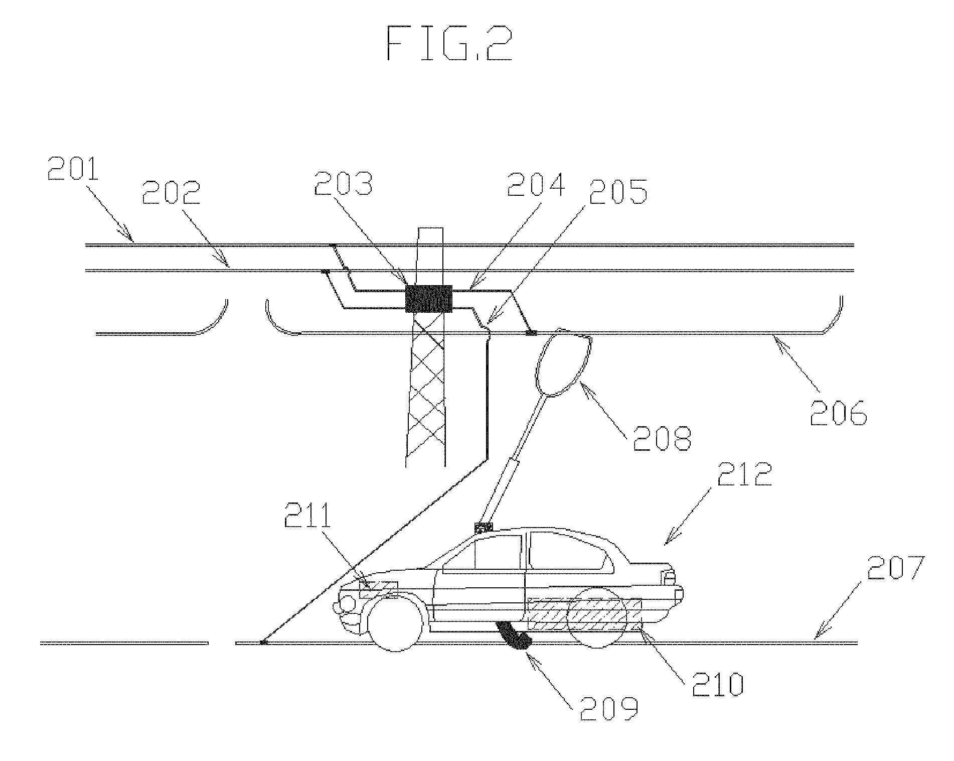
[0028]FIG. 2 is a side view schematically illustrating an electrical vehicle on an electrified roadway, which has converting means between electricity transmission power line and conductive line to convert high voltage AC into low voltage AC, according to the inventi...

Problems solved by technology

However, pollutants derived from automobile operation have posed serious environmental problems.
In this case, the vehicles have a very limited battery pack so that they are generally confined to the regions where the power cable is present and they have generally not been found on open roadways for general public use.
Due to the limitation of a battery capacity, a pure battery-operated vehicle typically has to reserve a huge portion of its weight for the battery pack.
Even so, a pure battery-operated vehicle still suffers serious limitation in the distance it can travel between battery charges.
Attempts at building viable battery-powered electric vehicles continued throughout the 1990s, but cost, speed and inadequate driving range made them uneconomical.
Although these patents have greatly improved this type of electrically operated transportation system, there are still some unanswered issues remaining, such as safety concern, installation and maintenance issue, and reduction of line loss during electricity transmission.
In addition, the traditional electrical pickup as seen on a trolley bus has some drawbacks, for instance, it is not easy to engage and disengage a vehicle with a power line and it does not allow other vehicles, which share the same power line, to pass by.
From the above, it is seen that the prior art electrically operated vehicle transportation systems have generally been inherently limited in some respects, which might have prevented their widespread acceptance.

Method used


Image

  • An electrical vehicle transportation system
  • An electrical vehicle transportation system
  • An electrical vehicle transportation system

Examples


Embodiment Construction

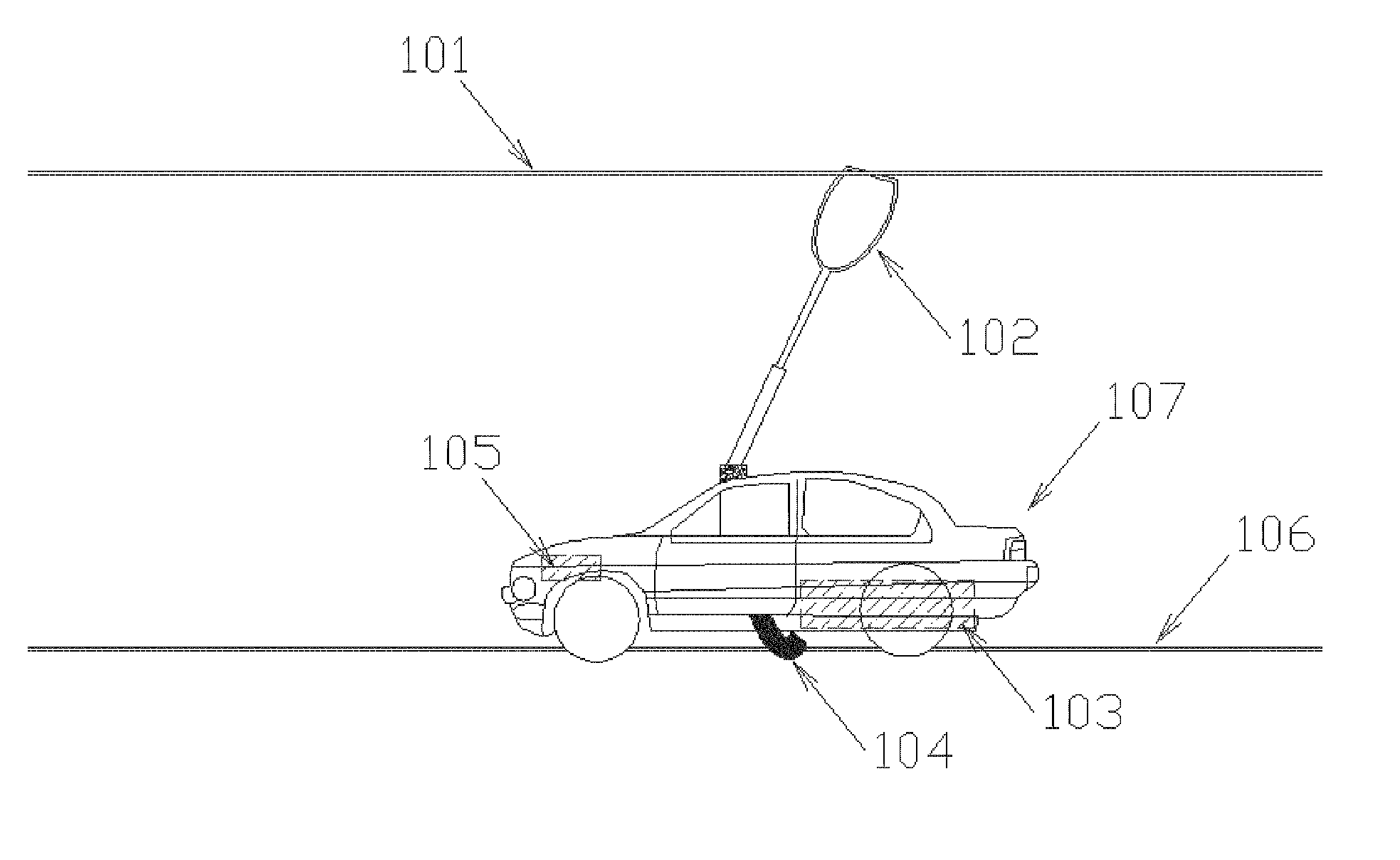
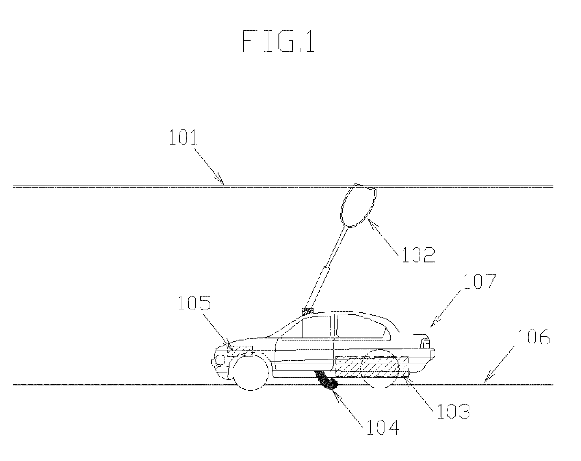
[0031] In this invention, two conductive lines, through which an electrical vehicle receives outside electricity, are located separately. The hot line (or the charged line) is deposited at a position above vehicles traveling on the roadway and the neutral line is deposited on the surface of the roadway. This arrangement provides several advantages over prior arts: 1) elimination of potential hazard to foot travelers; 2) elimination of accidental short circuit, which may be caused by rain or other incidents; 3) elimination of strict positioning of the vehicle on the roadway in order to receive outside power. It also makes possible for vehicles on different lanes to share a hot line and / or a neutral line.

[0032] In the preferred embodiments disclosed in FIGS. 2 and 3, the hot lines connect with a nearby high voltage electricity-transmission line through a converting means. In this case, one hot line covers only a segment of a roadway. As a result, each hot line can be manipulated indi...


PUM


Abstract

An improved electrically operated transportation vehicle and an electrified roadway over which the vehicle may operate and which supplies electric current to the vehicle are disclosed, in which hot power lines are located overhead of vehicles and neutral lines are deposited on the surface of the roadway. In addition, a high voltage AC line, extending continually along the roadway, is separated from a segmented low voltage AC or DC line. An improved electrical pickup is also disclosed to facilitate engagement and disengagement of a vehicle from a power supply line.

Description

BACKGROUND OF THE INVENTION [0001] 1. Field of the Invention [0002] This invention relates to electrically operated transportation vehicle systems, and more particularly to an improved electrically operated transportation vehicle and an electrified roadway over which the vehicle may operate and which supplies electric current to the vehicle. [0003] 2. Description of the Prior Art [0004] Vehicles, such as automobiles and trucks, have become indispensable tools of transportation for people. Based on different energy sources, vehicles were divided into two main categories: electrical vehicles and fuel-powered vehicles. The most commonly used fuels are gasoline and diesel oil. Although electrical powered vehicles were invented earlier, it was gasoline vehicles powered by an internal combustion engine that ushered in the age of modern automobiles. [0005] Many factors have contributed to the popularity of gasoline-powered vehicles. Among them, ease of refueling and range of travel without...

Claims


Application Information

Patent Timeline
IPC IPC(8): B60L5/04
CPCB60L5/18B60M1/36B60L5/42
Inventor LI, DINGZHONG
Owner LI DINGZHONG
Learn More