Space optimized coalescer

a coalescer and space technology, applied in the field of coalescers, can solve the problems of not being able to unable to simultaneously achieve all three in an acceptable fashion, and unable to achieve the effect of achieving the three in an acceptable fashion, and achieves the effects of high removal efficiency, long service life, and low pressure drop

Active Publication Date: 2007-03-22
CUMMINS FILTRATION IP INC
View PDF105 Cites 133 Cited by
  • Summary
  • Abstract
  • Description
  • Claims
  • Application Information

AI Technical Summary

Benefits of technology

[0004] In designing a coalescer, trade-offs often need to be made. For example, a) high removal efficiency or b) low pressure drop or c) long service life or d) small size can be achieved individually, but not necessarily in combination. The present invention addresses and reduces these trade-offs in combination.

Problems solved by technology

Diesel engine crankcase ventilation applications are extremely challenging from a filtration point of view.
Low restriction and long service life are required.
However, current coalescer design practices and products fall short of these requirements, in that high removal efficiency or long service life or small size can be achieved, but current practice has been unable to simultaneously achieve all three in an acceptable fashion.
The design challenge for crankcase ventilation coalescers, indeed for all types of coalescers, is to maximize the amount of contaminant that can be removed and held within a given volume.
With pleated media there is much wasted space between pleats.
This results in increased pressure drop, inefficient utilization of media surface area, and decreased life.
While less susceptible to plugging than pleated media when coalescers of equivalent upstream media face area are compared, circular depth coalescers tend to be more susceptible to plugging than pleated media coalescers of the same size, because less face area can be packaged into the same volume.
For coalescer media thicker than 3 to 7 mm, the additional thickness beyond the optimal contributes to Region 2 and does not improve removal significantly while increasing the pressure drop.
Further, in the presence of contaminant, whether solids or droplets, the greatest contaminant buildup on the media occurs on the upstream side further increasing the local restriction.
The disadvantage is decreased life, since there is less media face area on the upstream side to hold solids that may plug the coalescer.
Coalescers are subject to solids plugging and shortened service life in applications with significant levels of solids.
Pleated elements are particularly well suited in this regard, while circular depth media elements suffer due to the relatively small media face area in the upstream internal cavity.
The design challenge for coalescers is to maximize the amount of contaminant that can be removed within a given volume.

Method used


Image

  • Space optimized coalescer
  • Space optimized coalescer
  • Space optimized coalescer

Examples


Embodiment Construction

.S. patent application Ser. No. 11 / 230,694

[0044] The following description regarding FIGS. 1-25 is taken from the noted '694 application.

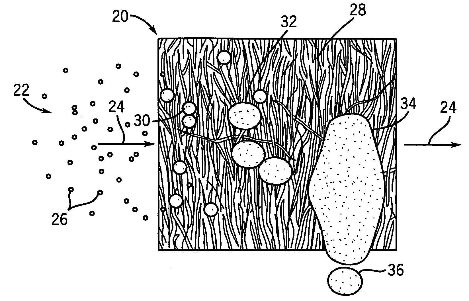
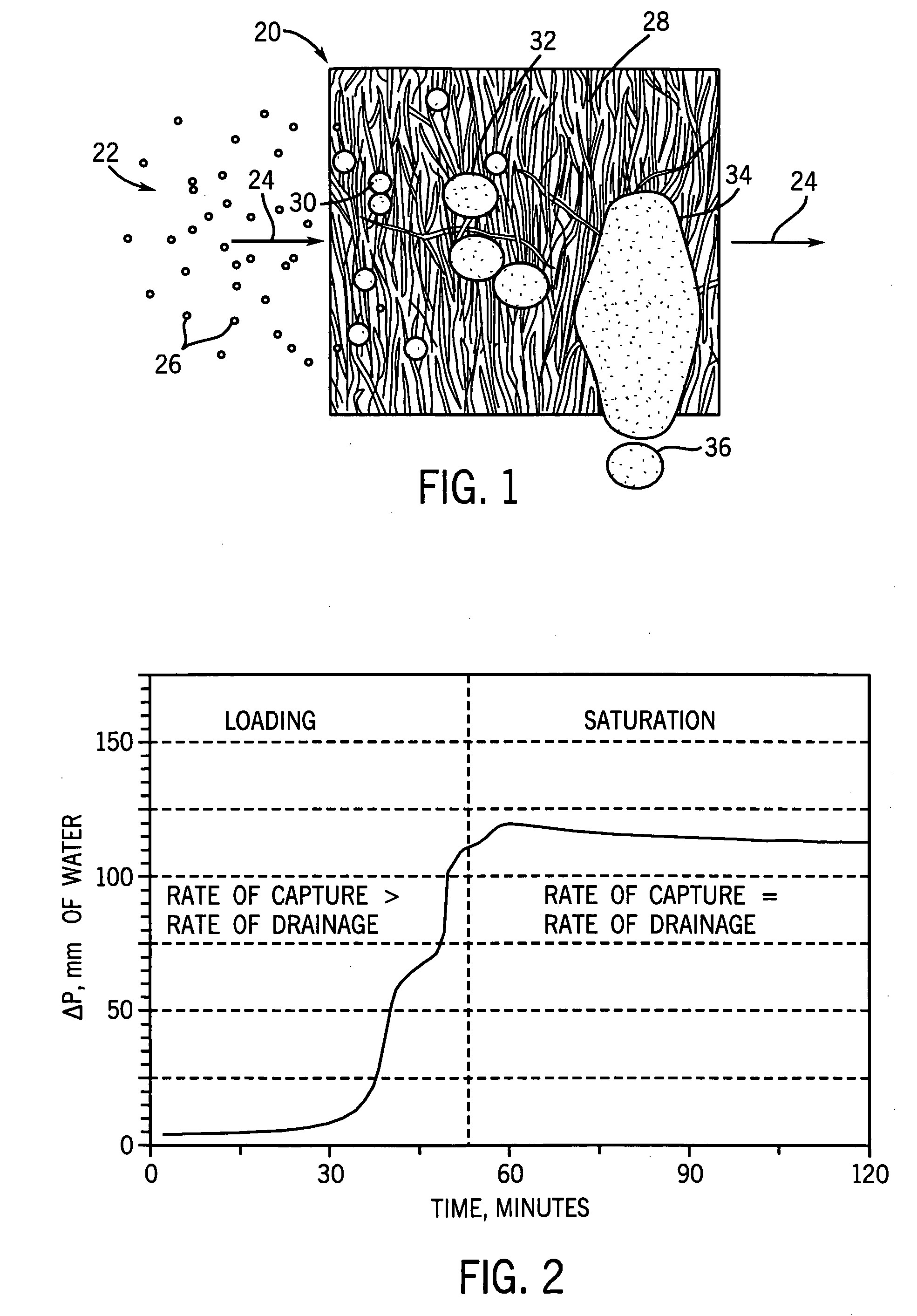
[0045]FIG. 1 shows a coalescer 20 for coalescing a medium 22 having two immiscible phases, namely a continuous phase 24 and a dispersed phase 26. For example, in the case of an engine crankcase ventilation coalescer, the continuous phase 24 is air, and the dispersed phase is oil, e.g. in the form of a fine mist having droplets 26 of about one micron and smaller in diameter. The continuous phase 24 flows from upstream to downstream, i.e. left to right in FIG. 1. The coalescer includes fibrous media 28 capturing droplets of the dispersed phase, coalescingly growing the droplets into larger drops, for example as shown at 30, 32, which further coalesce and grow to form pools such as 34 which drain as shown at 36. Within the gas or air stream 24, droplets 26 can collide and grow in size by drop to drop coalescence. Upon entry into coalescer 20, the dro...


PUM

PropertyMeasurementUnit
diameteraaaaaaaaaa
βaaaaaaaaaa
βaaaaaaaaaa

Abstract

A coalescer is provided minimizing trade-offs among high removal efficiency, low pressure drop, long service life, and small size.

Description

CROSS-REFERENCE TO RELATED APPLICATIONS [0001] This application is a continuation-in-part of U.S. Patent application Ser. No. 11 / 273,101, filed Nov. 14, 2005, and a continuation-in-part of U.S. patent application Ser. No. 11 / 230,694, filed Sep. 20, 2005.BACKGROUND AND SUMMARY [0002] The invention relates to coalescers. [0003] Coalescers are known in the prior art for coalescing a medium having two immiscible phases, namely a continuous phase and a dispersed phase. For example: in engine crankcase ventilation systems, and other air-oil separation systems, the continuous phase is air, and the dispersed phase is oil; in fuel-water separation systems, such as fuel filters, fuel is the continuous phase, and water is the dispersed phase; in water-oil separation systems, water is the continuous phase, and oil is the dispersed phase. The coalescer element has coalescer media capturing droplets of the dispersed phase, coalescingly growing the droplets into larger drops which further coalesce...

Claims


Application Information

Patent Timeline
Patent Type & Authority Applications(United States)
IPC IPC(8): B01D17/02
CPCB01D17/045Y10S55/19B01D46/0001B01D46/003B01D46/106B01D46/521B01D2239/0216B01D2239/0622B01D2239/065B01D2239/0695B01D2239/1291B01D2275/10B01D2275/105B01D2275/205B01D2275/206B01D2275/207B01D2275/208B01D2275/30B01D39/1623B01D17/10
Inventor SCHWANDT, BRIAN W.VERDEGAN, BARRY M.ZOCH, ROGER L.FEDOROWICZ, JEFFREY A.BADEAU, KURT M.A.MUSE, ROBERT E.HERMAN, PETER K.
Owner CUMMINS FILTRATION IP INC
Why Eureka
Try Eureka