
Electrical vehicle controller

a technology of electric vehicle controller and controller, which is applied in the direction of dynamo-electric converter control, multiple dynamo-motor starters, electric devices, etc., can solve the problems of slipping of wheels and idle running of wheels, and achieve simple and rapid/accurate torque correction control, the effect of reducing the torque pattern

Inactive Publication Date: 2007-03-22
MITSUBISHI ELECTRIC CORP
View PDF5 Cites 5 Cited by
  • Summary
  • Abstract
  • Description
  • Claims
  • Application Information

AI Technical Summary

Benefits of technology

[0007] According to the invention, the second frequency deviation is subtracted from the first frequency deviation to calculate the idle running frequency deviation that varies only under the idle running state, and the idle running frequency deviation and the idle running detecting set value are compared with each other to output the idle running detection signal. Therefore, the idle running detection can be instantaneously performed without being affected by a wheel diameter difference, and there can be achieved an effect that simple and rapid / accurate torque correction control can be performed.BEST MODES FOR CARRYING OUT THE INVENTION First Embodiment
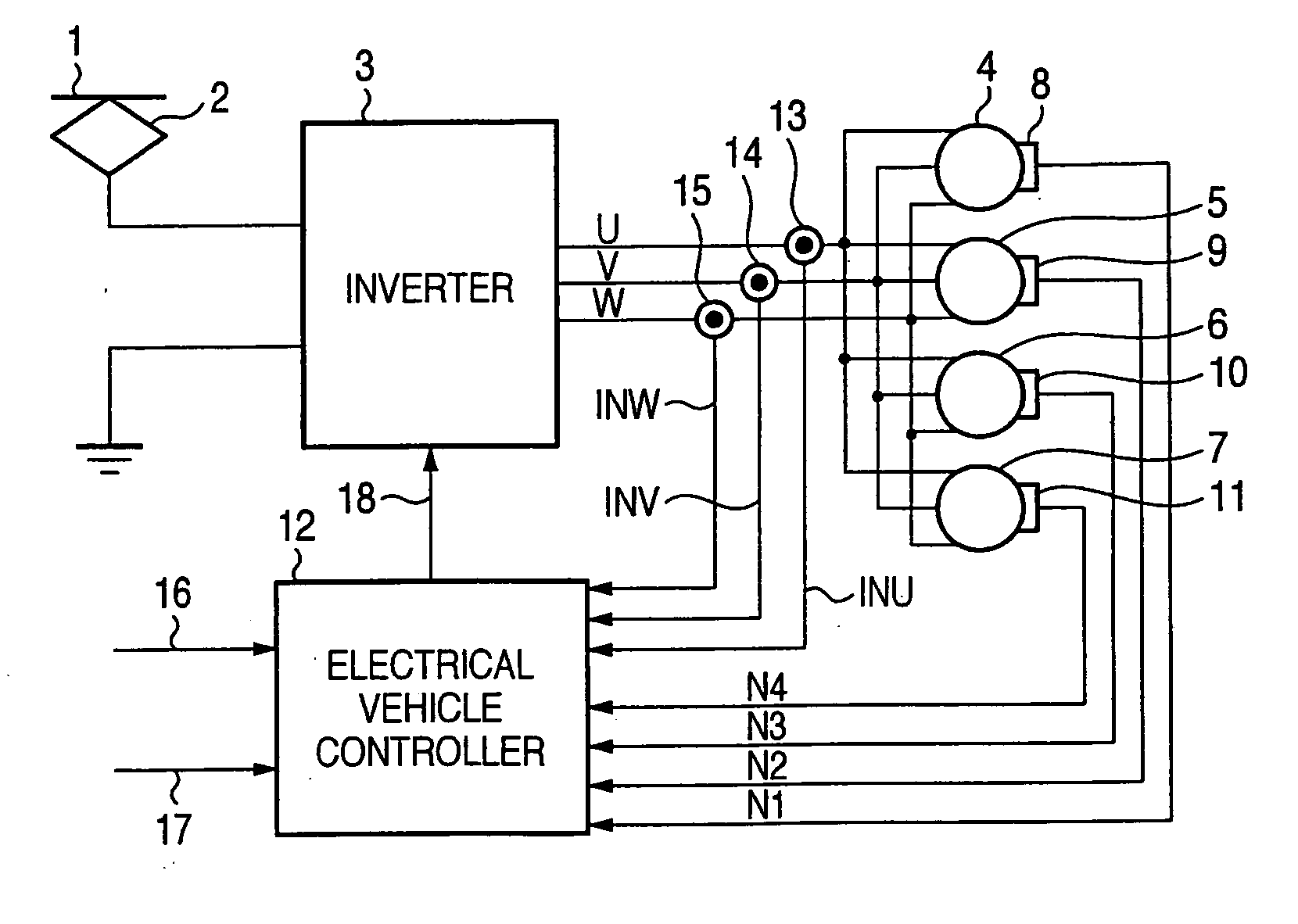
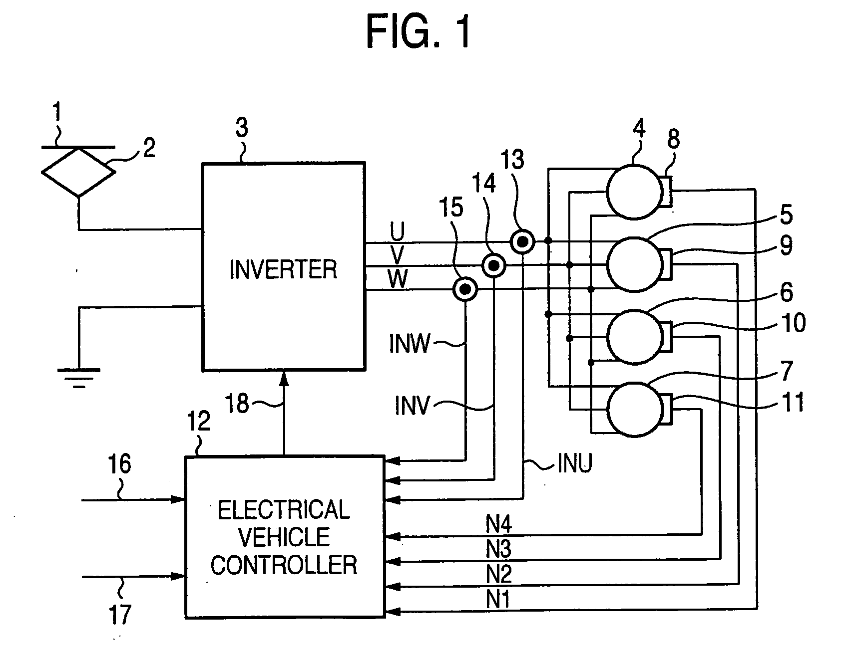
[0008]FIG. 1 is a construction diagram showing the relationship of an electrical vehicle controller, an inverter and AC electric motors according to a first embodiment. In FIG. 1, DC power collected from an overhead wire 1 through power collector 2 is supplied to an inverter 3 and converted to three-phase AC power of U-phase, V-phase and W-phase. AC electric motors 4 to 7 for an electrical vehicle such as induction motors or the like are driven by the three-phase AC power as the output of the inverter 3. The rotational numbers N1 to N4 of the respective AC electric motors 4 to 7 which are detected by pulse generators 8 to 11 are input to an electrical vehicle controller 12. Furthermore, input current INU, INV, INW of the AC electric motors 4 to 7 which are detected by current detectors 13 to 15 are input to the electrical vehicle controller 12. Furthermore, a driver's platform instruction signal 16 of a power running notch instruction from a driver's platform (not shown) and a load weighting instruction signal 17 from a load weighting device (not shown) are input to the electrical vehicle controller 12. q-axis current control of the inverter 3 is carried out by a q-axis current control signal 18 output from the electrical vehicle controller 12.
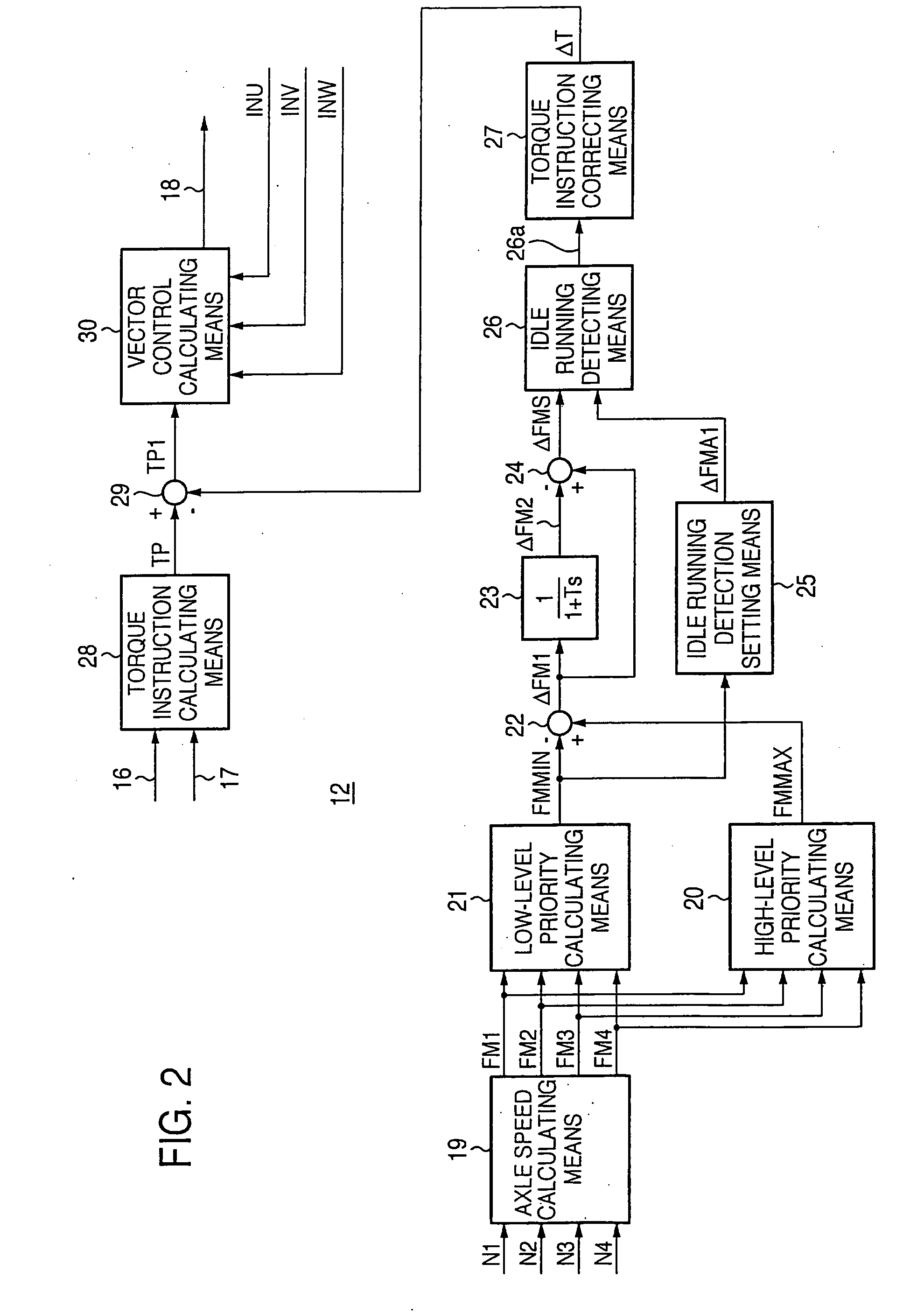
[0009]FIG. 2 is a block diagram showing an internal construction of the electrical vehicle controller 12 according to a first embodiment implementing the invention. In FIGS. 1 and 2, in the axle speed calculating means 19, the frequencies FM1 to FM4 corresponding to the respective axle speeds of the axles (not shown) which are directly connected to the wheels (not shown) are calculated from the rotational numbers N1 to N4 of the AC electric motors 4 to 7 detected by the pulse generators 8 to 11. The high-level priority calculating means 20 extracts the maximum frequency FMMAX corresponding to the axle speed of the axle directly connected to the minimum-diameter wheel. Furthermore, the low-level priority calculating means 21 likewise extracts the minimum frequency FMMIN from the respective frequencies FM1 to FM4. Subsequently, the minimum frequency FMMIN is subtracted from the maximum frequency FMMAX in a first subtracter 22 to calculate a first frequency deviation ΔFM1.
[0010] The first frequency deviation ΔFM1 is input to primary delay means 23 as a primary delay system to calculate a second frequency deviation ΔFM2. Subsequently, in a second subtracter 24, the second frequency deviation ΔFM2 is subtracted from the first frequency deviation ΔFM1 to calculate an idle running frequency deviation ΔFMS.
[0011] Furthermore, an idle running detecting set value ΔFMA1 for judging the idle running at the frequency level is output from idle running detection setting means 25. In idle running detecting means 26, the idle running frequency deviation ΔFMS and the idle running detection setting value ΔFMA1 are compared with each other, and when the idle running frequency deviation ΔFMS is larger than the idle running detection setting value ΔFMA1, the idle running detecting means 26 outputs an idle running detection signal 26a having the analog amount corresponding to the difference between the idle running frequency deviation and the idle running detection setting value. In a torque instruction correcting means 27 to which the idle running detection signal 26a is input, a torque correction amount ΔT of a torque pattern is calculated in accordance with the idle running detection signal 26a.
[0012] Furthermore, a driver's platform instruction signal 16 corresponding to power running notch instructed from a driver's platform at the power running time of the electrical vehicle and a load weighting instruction signal 17 corresponding to the weight of the electrical vehicle are input to a torque instruction calculating means 28. In the torque instruction calculating means 28, a torque instruction signal TP corresponding to the torque to be output the AC electric motors 4 to 7 is output from both the instruction signals 16, 17. The torque instruction correcting means 29 outputs only when idle running occurs, and it subtracts the torque correction amount ΔT from the torque instruction signal TP to narrow down the torque instruction correcting signal TP1. Subsequently, vector control calculating means 30 calculates the q-axis current corresponding to the torque of the AC electric motors 4 to 7 on the basis of the input current INU, INV, INW of the AC electric motors 4 to 7 and the torque instruction correction signal TP1, and outputs a q-axis current control signal 18. The inverter 3 reduces the torque pattern on the basis of the q-axis current control signal 18 to carry out idle running re-adhesion control.

Problems solved by technology

However, when a driving force larger than the adhesive force is applied at the starting time of the AC electric motor, idle running of wheels occurs.
On the other hand, when a braking force larger than the adhesive force is applied at the braking time, slip of the wheels occurs.

Method used


Image

  • Electrical vehicle controller
  • Electrical vehicle controller
  • Electrical vehicle controller

Examples


first embodiment

[0008]FIG. 1 is a construction diagram showing the relationship of an electrical vehicle controller, an inverter and AC electric motors according to a first embodiment. In FIG. 1, DC power collected from an overhead wire 1 through power collector 2 is supplied to an inverter 3 and converted to three-phase AC power of U-phase, V-phase and W-phase. AC electric motors 4 to 7 for an electrical vehicle such as induction motors or the like are driven by the three-phase AC power as the output of the inverter 3. The rotational numbers N1 to N4 of the respective AC electric motors 4 to 7 which are detected by pulse generators 8 to 11 are input to an electrical vehicle controller 12. Furthermore, input current INU, INV, INW of the AC electric motors 4 to 7 which are detected by current detectors 13 to 15 are input to the electrical vehicle controller 12. Furthermore, a driver's platform instruction signal 16 of a power running notch instruction from a driver's platform (not shown) and a load ...

second embodiment

[0014]FIG. 4 is a block diagram showing an electrical vehicle controller 12 according to a second embodiment of the invention. In FIG. 4, 16 to 22, 28 to 30 represent the same elements as the first embodiment. In FIGS. 1 and 4, the first frequency deviation ΔFM1 is calculated in the first subtracter 22 as in the case of the first embodiment. When the first frequency deviation ΔFM1 is input to first time-differentiating means 31, a first time variation amount ΔFM1D is calculated by time-differentiating the first frequency deviation ΔFM1 from a predetermined time measurement start time for a predetermined time t1. Furthermore, the first frequency deviation ΔFM1 is input to second time-differentiating means 32, and time-differentiated from a predetermined time measurement start time for a predetermined time t2 longer than the time t1 to calculate a temporary time variation amount ΔFM2D(t2).

[0015] Subsequently, in converting means 33, the temporary time variation amount ΔFM2D(t2) is co...

third embodiment

[0018]FIG. 6 is a block diagram showing an electrical vehicle controller 12 according to a third embodiment. In FIGS. 1 and 6, 16 to 24, 28 to 30 represent the same elements as the first embodiment.

[0019] In FIGS. 1 and 6, the first frequency deviation ΔFM1 is calculated in the first subtracter 22 as in the case of the first embodiment. Furthermore, the first frequency deviation ΔFM1 is input to the primary delay means 23, and the second frequency deviation ΔFM2 is calculated as the primary delay system. Subsequently, in the second subtracter 24, the second frequency deviation ΔFM2 is subtracted from the first frequency deviation ΔFM1 to calculate the idle running frequency deviation ΔFMS. Then, the idle running detection set value ΔFMA2 for judging the idle running at the frequency level is output from the idle running detection setting means 38. In this embodiment, the idle running detection set value ΔFMA2 is set by a predetermined value, for example so that the acceleration is ...


PUM


Abstract

The maximum frequency and the minimum frequency are extracted from frequencies corresponding to respective axle speeds. The minimum frequency is subtracted from the maximum frequency to achieve a first frequency deviation, and also the first frequency deviation is input as a primary delay system to achieve a second frequency deviation. Furthermore, the second frequency deviation is subtracted from the first frequency deviation to achieve an idle running detection setting deviation, and also an idle running detection set value for judging the idle running of the wheels at the frequency level is achieved. The idle running frequency deviation and the idle running detection set value are compared with each other to output an idle running detection signal, and also a torque correction amount of an AC electric motor is calculated on the basis of the idle running detection signal.

Description

FIELD OF THE INVENTION [0001] The present invention relates to an electrical vehicle controller for controlling idle running of an electrical vehicle driven by an AC electric motor. BACKGROUND ART [0002] An electrical vehicle is normally accelerated and decelerated by the adhesive force between each wheel and a rail. However, when a driving force larger than the adhesive force is applied at the starting time of the AC electric motor, idle running of wheels occurs. On the other hand, when a braking force larger than the adhesive force is applied at the braking time, slip of the wheels occurs. Therefore, the acceleration / deceleration performance of electrical vehicles has been hitherto enhanced by detecting idle running / slip and reducing occurring torque of the AC electric motor to rapidly induce re-adhesion. For example, according to Patent Document 1, the average speed of the rotational velocities of plural AC electric motors is first calculated, a wheel diameter difference correcti...

Claims


Application Information

Patent Timeline
IPC IPC(8): H02P5/00B60L9/18H02P5/74
CPCB60L2200/26B60L3/10B60L9/18
Inventor YOKOZUTSUMI, RYONEGORO, HIDETO
Owner MITSUBISHI ELECTRIC CORP
Learn More