Storage device

Inactive Publication Date: 2007-03-22
TOSHIBA STORAGE DEVICE CORP
View PDF20 Cites 0 Cited by
  • Summary
  • Abstract
  • Description
  • Claims
  • Application Information

AI Technical Summary

Benefits of technology

[0013] Accordingly, it is a general object of the present invention to provide a novel and useful storage device.
[0014] Another and more specific object of the present invention is to provide a storage device whereby a driving electrical current proper for unlatching a head can be applied to a head moving mechanism by measuring an unlatch force necessary for unlatching the head and whereby a storage device having a latch mechanism whose latch force is smaller than a designed value at the time when the storage device is shipped can be identified.
[0021] According to the above-mentioned invention, it is possible to provide a storage device whereby a driving electrical current proper for unlatching a head can be applied to a head moving mechanism by measuring an unlatch force necessary for unlatching the head and whereby a storage device having a latch mechanism whose latch force is smaller than a designed value at the time when the storage device is shipped can be identified.

Problems solved by technology

However, if an excessive driving electrical current, which applies an unlatch force larger than necessary as compared to the latch force applied by the latch mechanism to the magnetic head, is applied to the head moving mechanism of the magnetic head, the ramp may be worn down due to drastic movement of the magnetic head so that fine particles may be generated, the magnetic head may be damaged due to an insufficient floating amount of the magnetic head above the ramp, or a large mechanical noise may be generated when the magnetic head is moved.
Therefore, even if a magnetic disk apparatus has a latch mechanism whose actual latch force is smaller than a designed value due to bad parts or bad installation, the magnetic disk apparatus may be shipped.
This may cause the magnetic head to become adhered on the magnetic disk in a case where the magnetic disk is not being rotated.
In addition, in a magnetic disk apparatus whose latch force is smaller than the designed value, if a driving electrical current is applied whose value is sufficient for unlatching a magnetic head in a case where the latch force has the designated value, as discussed above, excessive driving electrical current may be applied to the head moving mechanism.
In other words, in the conventional art, a driving electrical current proper for unlatching the magnetic head cannot be applied to the head moving mechanism for every magnetic driving apparatus.
Furthermore, it is not possible to identify storage devices having a latch mechanism whose latch force is smaller than a designed value at the time when the storage devices are shipped.

Method used


Image

  • Storage device
  • Storage device
  • Storage device

Examples


example

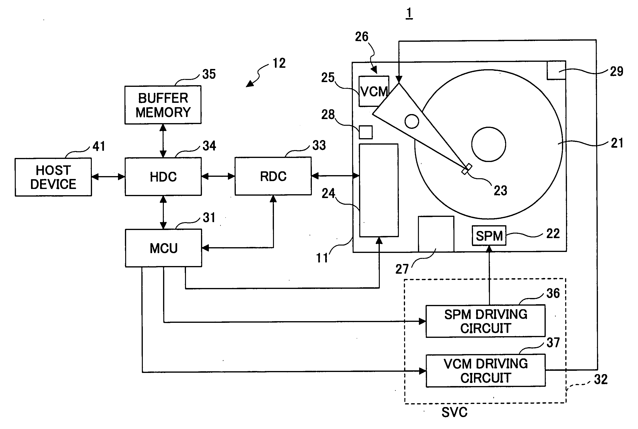
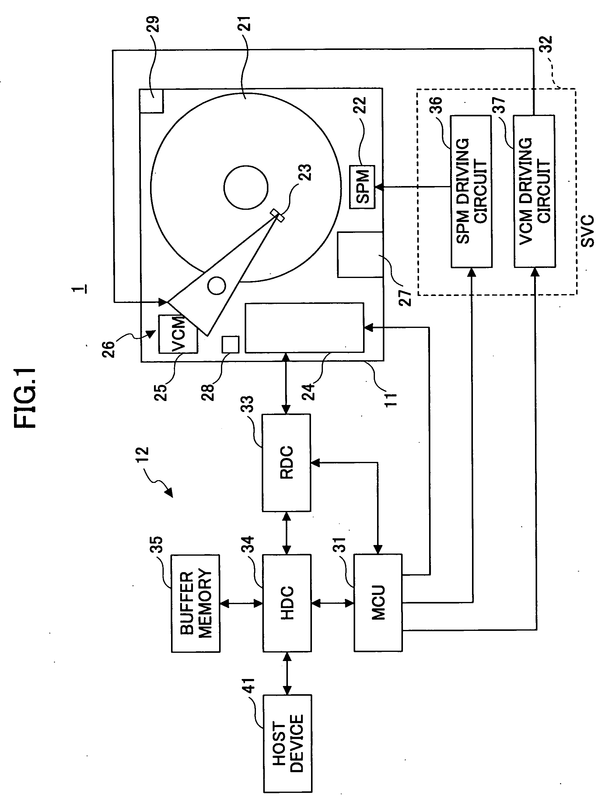
[0043]FIG. 1 is a block diagram showing a main part of a storage device of an example of the present invention. In this example, the present invention is applied to a magnetic disk apparatus.

[0044] Referring to FIG. 1, a magnetic disk apparatus 1 includes a disk enclosure (hereinafter “DE”) 11 and a printed circuit board (hereinafter “PCB”) 12.

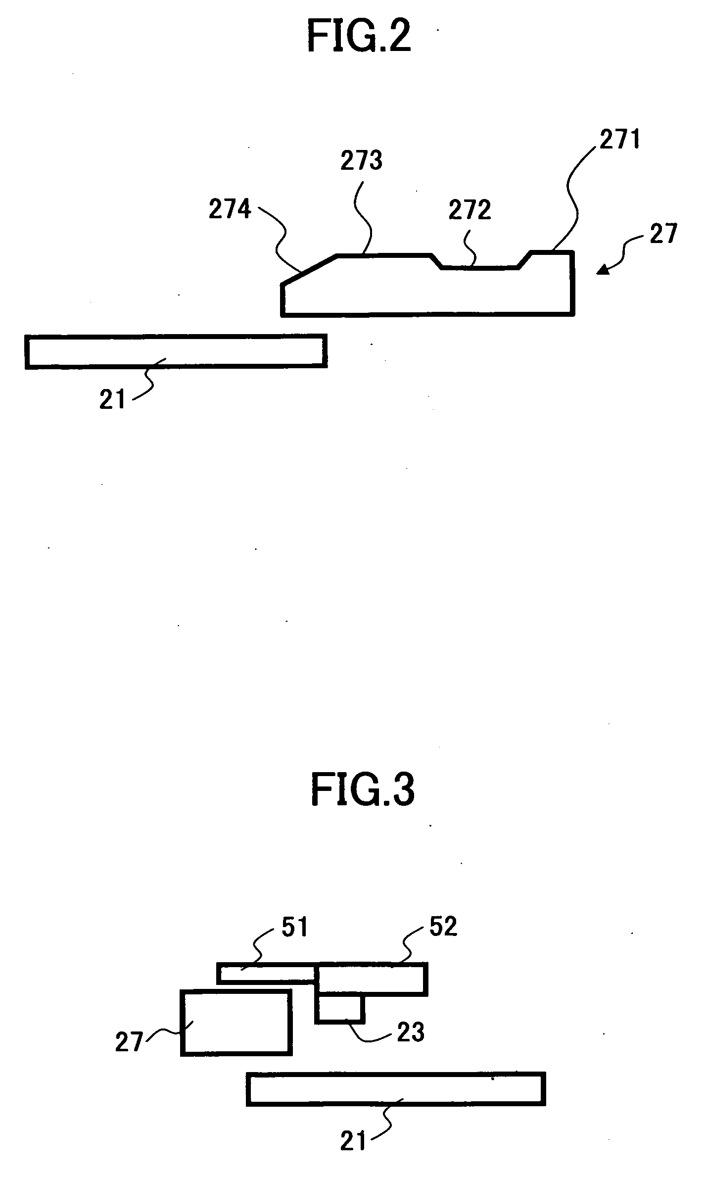
[0045] The DE 11 includes a single or plural magnetic disk(s) 21, a spindle motor (hereinafter “SPM”) 22, a single or plural magnetic head(s) 23, a head amplifier 24, a head moving mechanism 26 including a voice coil motor (hereinafter “VCM”) 25, a ramp mechanism 27, a latch mechanism 28, a temperature sensor 29, and the like.

[0046] The SPM 22 rotates the magnetic disk 21. The magnetic head 23 is provided so as to correspond to the magnetic disk 21. The VCM 25 moves the magnetic head 23. The latch mechanism 28 latches the magnetic head 23 to a parking position of the ramp mechanism 27 by a magnet or the like. Temperature inside of the DE 11...


PUM


Abstract

A storage device configured to load and unload a head against a storage medium, includes a latch mechanism configured to latch the unloaded head, a head moving mechanism configured to move the head, a measuring part configured to measure an unlatch force necessary for unlatching the head latched by the latch mechanism, by applying a constant electrical current to the head mechanism so that the head is moved in a load direction, by measuring a back electromotive voltage, and calculating a moving speed and acceleration of the head, a storing part configured to store information indicating the measured unlatch force in the storage device, and a control part configured to apply a driving electrical current corresponding to the stored information to the head moving mechanism where the head is latched by the latch mechanism at the time of loading.

Description

BACKGROUND OF THE INVENTION [0001] 1. Field of the Invention [0002] The present invention generally relates to storage devices, and more specifically, to a storage device having a latch mechanism configured to latch an unloaded head in a structure where the head can be loaded or unloaded against a recording medium. [0003] 2. Description of the Related Art [0004] In a magnetic disk apparatus having a ramp mechanism, a magnetic head is loaded on a magnetic disk from a parking position of the ramp mechanism via a ramp. The magnetic head on the magnetic disk is unloaded to the parking position via the ramp of the ramp mechanism. The magnetic head situated on the parking position is latched to the parking position by a latch mechanism formed by a magnet or the like so that the magnetic head is prevented from moving on the ramp or the magnetic disk carelessly. [0005] Therefore, at the time of unloading, it is necessary to control the head moving mechanism so that the magnetic head is driv...

Claims


Application Information

Patent Timeline
IPC IPC(8): G11B21/02
CPCG11B5/54G11B21/22G11B21/12
Inventor YAMASHITA, SATOSHIHARA, TAKESHIOBARA, YOSHIFUMI
Owner TOSHIBA STORAGE DEVICE CORP
Why Eureka
Try Eureka