Method for warped image object recognition

a technology of object recognition and warped images, applied in the field of computer vision object recognition, can solve the problems of space-variant object distortion, and increased computational burden and cos

Inactive Publication Date: 2007-03-22
GM GLOBAL TECH OPERATIONS LLC
View PDF13 Cites 36 Cited by
  • Summary
  • Abstract
  • Description
  • Claims
  • Application Information

AI Technical Summary

Benefits of technology

[0008] In accordance with another aspect of the present invention, a method for calculating undistorted integral features directly from a distorted input image for use in a computer vision object recognition system trained on undistorted images includes providing a Jacobian determinant relating a distorted image space to an undistorted image space, calculating and storing an integral image from the distorted input image, and calculating undistorted integral features using Jacobian integral image values based on the distorted image and the provided Jacobian determinant. Undistorted integral features may be calculated by integrating over a predetermined region the product of the distorted image and the Jacobian determinant. Further, undistorted integral features may be rapidly calculated by referencing a plurality of integral image values of the integral image delimited by the predetermined region, factoring the referenced integral image values by the Jacobian determinant, and algebraically combining the factored integral image values.
[0009] In accordance with another aspect of th

Problems solved by technology

Projections of such wide-angle scenes onto a two-dimensional image necessarily results in space-variant distortions of objects, especially near the edges of the image.
Known approaches to object recognition require either that multiple classifiers be trained for different spatial regions in the image or a co

Method used


Image

  • Method for warped image object recognition
  • Method for warped image object recognition
  • Method for warped image object recognition

Examples


Embodiment Construction

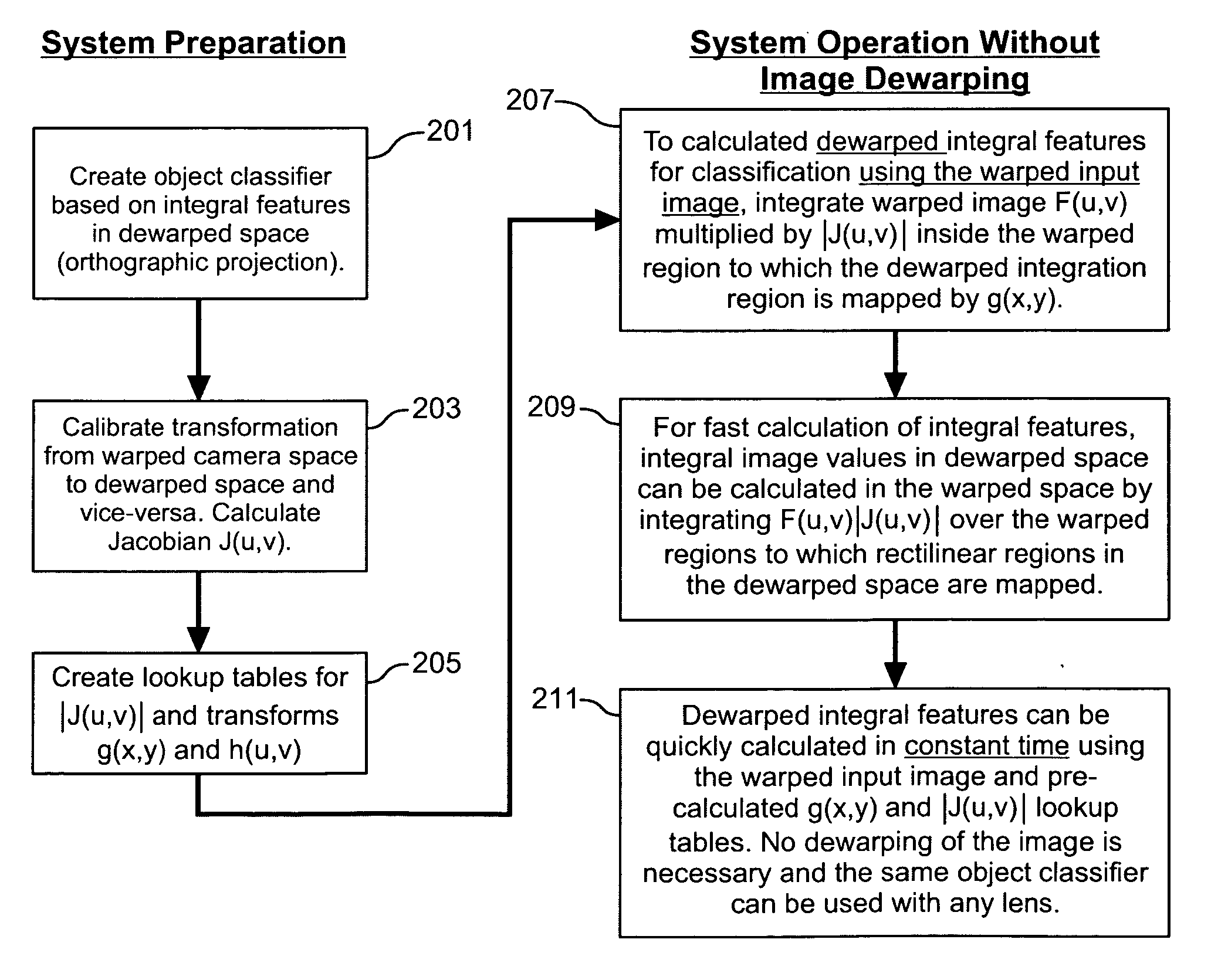
[0020] As used herein, the terms warped and distorted may be use interchangeably and the terms dewarped, unwarped and undistorted may be used interchangeably.

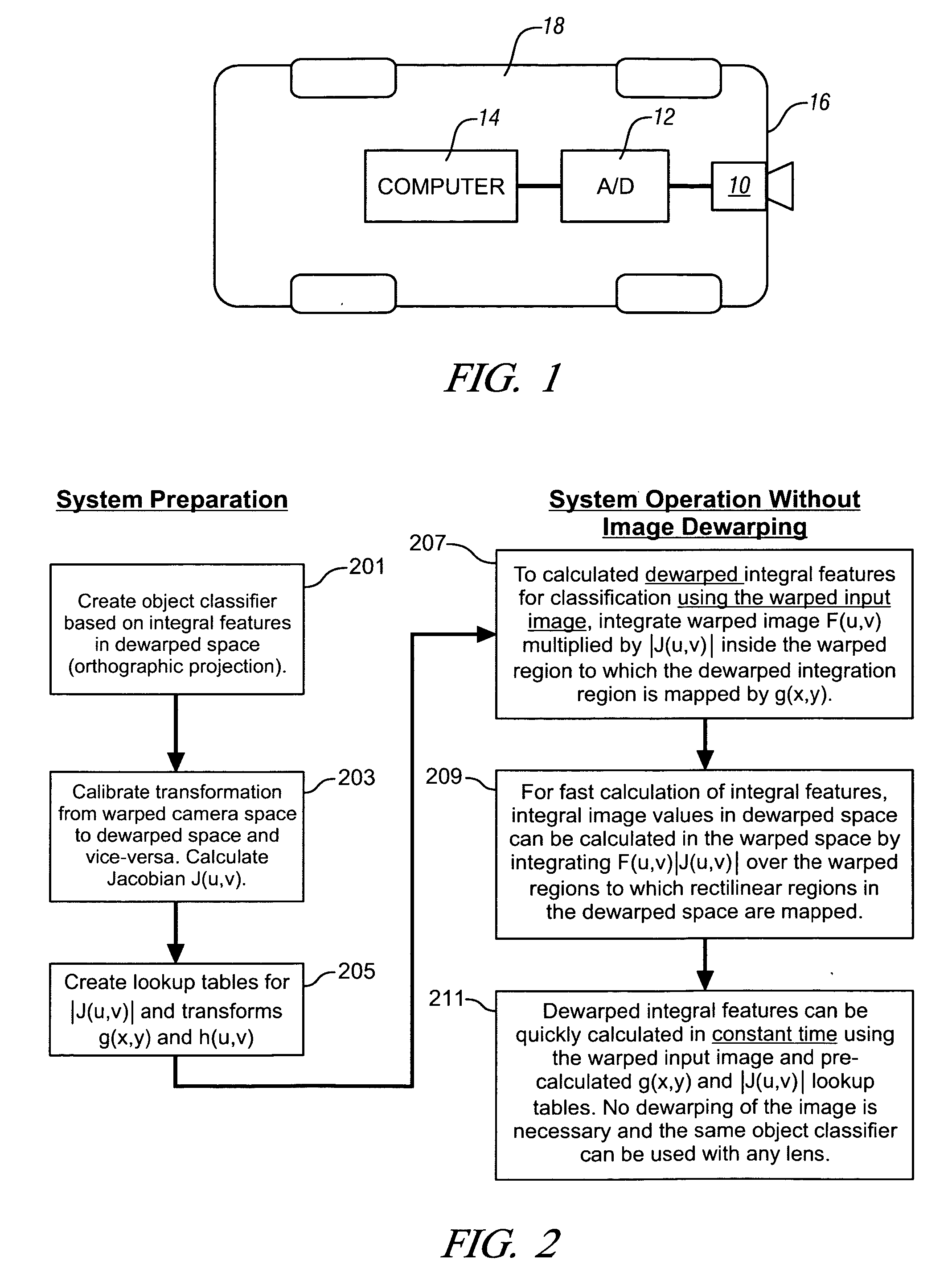
[0021] As shown in FIG. 1, exemplary hardware used to implement the method of the invention comprises a black and white, color, or near-IR CCD video camera 10 including wide-angle optics, such as what is commonly referred to a fish-eye lens. Such a camera can be mounted in an appropriate location for the particular application. In the present exemplary implementation, the camera 10 is shown mounted to the rear portion 16 of a vehicle 18. An analog-to-digital converter 12 couples the camera output to a computer 14. Alternative hardware arrangements will be apparent to those having ordinary skill in the art and may include, for example, catadioptric optics including semi-spherical or other curvature mirrors for reflective image collection, or video sensors having integrated CCD elements and digitization circuitry.

[0022] The com...


PUM


Abstract

A computer vision system includes distorting optics producing distorted or warped input images. The system includes an integral feature object classifier trained using an undistorted image space. Undistorted integral feature values are calculated directly from distorted input images without undistorting or dewarping the distorted input image.

Description

TECHNICAL FIELD [0001] The present invention is related to computer vision object recognition. More particularly, the invention is concerned with object recognition from distorted images. BACKGROUND OF THE INVENTION [0002] Certain computer vision systems require wide field of view. For example, in one automotive application, it is desirable to sense wide fields around the vehicle for pedestrians, vehicles, and other objects for collision warning, avoidance, and mitigation. Detecting landmarks visually and enhancing situational awareness and vehicle location accuracy is another automotive application. Very wide angle occupant sensing for security, child monitoring, and smart airbag systems are yet other examples of automotive applications. Surveillance and perimeter security are examples of other non-automotive applications. In all of these applications and others not separately mentioned, it is generally thought to be cost-effective and efficient from a packaging perspective to use ...

Claims


Application Information

Patent Timeline
IPC IPC(8): G06K9/46G06K9/32G06V10/32G06V10/40
CPCG06K9/46G06K9/42G06V10/32G06V10/40
Inventor OWECHKO, YURIMEDASANI, SWARUP
Owner GM GLOBAL TECH OPERATIONS LLC
Why Eureka
Try Eureka