Fiber-optics multiplexed interferometric current sensor
a fiber optics and current sensor technology, applied in the field of current sensors, can solve the problems of unidentifiable harmonic analysis of electrical power, still has critical flaws, and cts have the risk of electric shock when monitoring high-voltage power lines, and achieve the effect of lowering equipment costs
- Summary
- Abstract
- Description
- Claims
- Application Information
AI Technical Summary
Benefits of technology
Problems solved by technology
Method used
Image

Examples
first embodiment
The First Embodiment
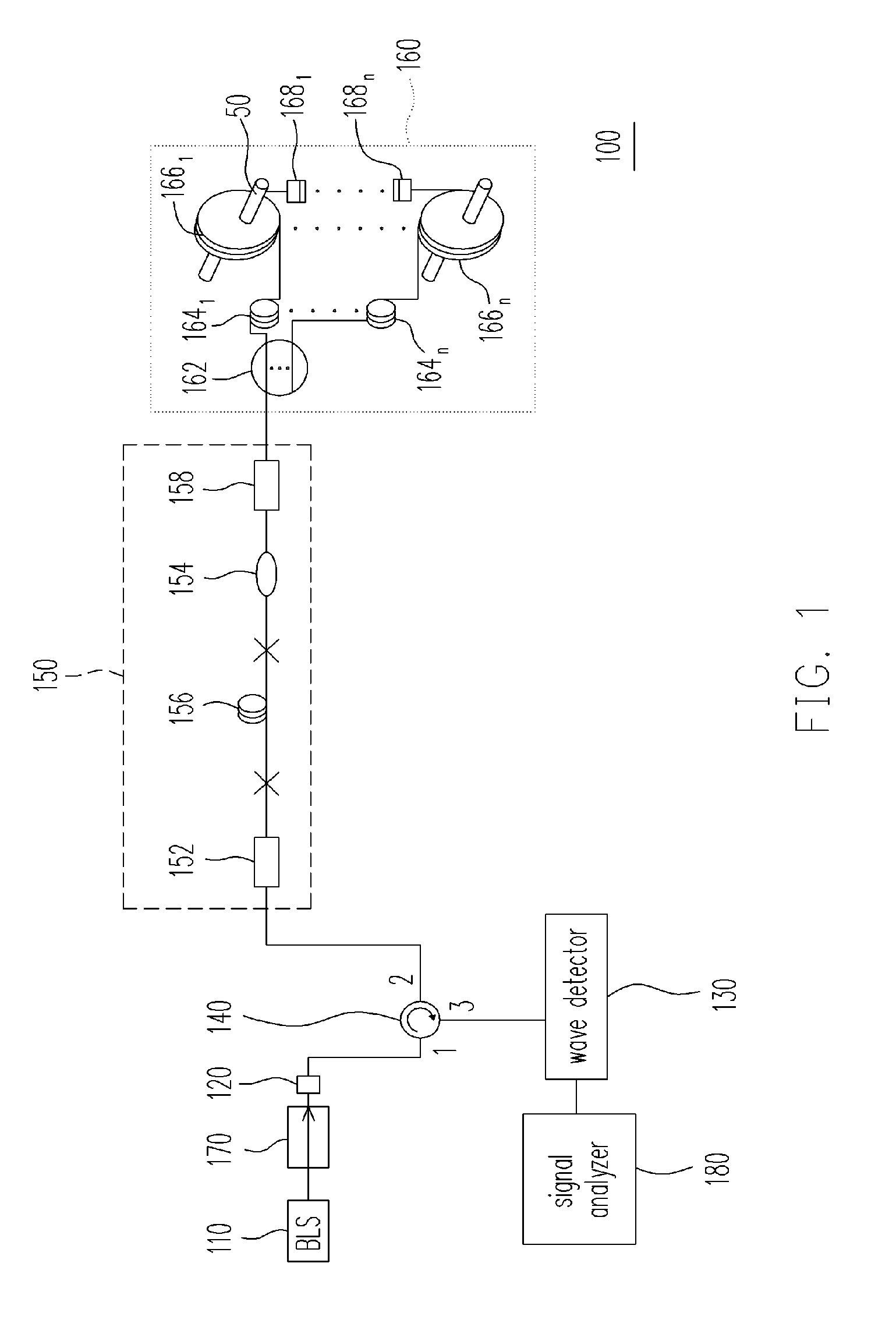
[0031]FIG. 1 is a schematic structural diagram of a fiber-optics multiplexed interferometric current sensor according to the first embodiment of the invention. Referring to FIG. 1, the fiber-optics multiplexed interferometric current sensor 100 according to the first embodiment of the invention is adapted for simultaneously sensing current intensities, frequencies, phases and waveforms loaded by a plurality of wires 50. The fiber-optics multiplexed interferometric current sensor 100 includes a broadband light source (BLS) 110, a depolarizer 120, a wave detector 130, an optical spliter 140, a passive demodulating interferometric module 150, and a sensor module array 160. The BLS 110 is adapted for providing a light wave, and the depolarizer 120 is coupled to the BLS 110. The optical spliter 140 includes a first port, a second port and a third port. The depolarizer 120 and the wave detector 130 are respectively coupled to the first port and the third port of the op...
second embodiment
The Second Embodiment
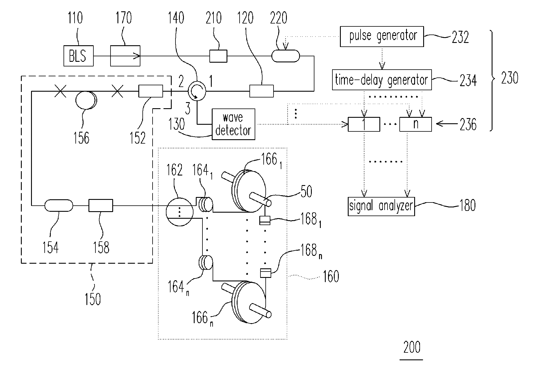
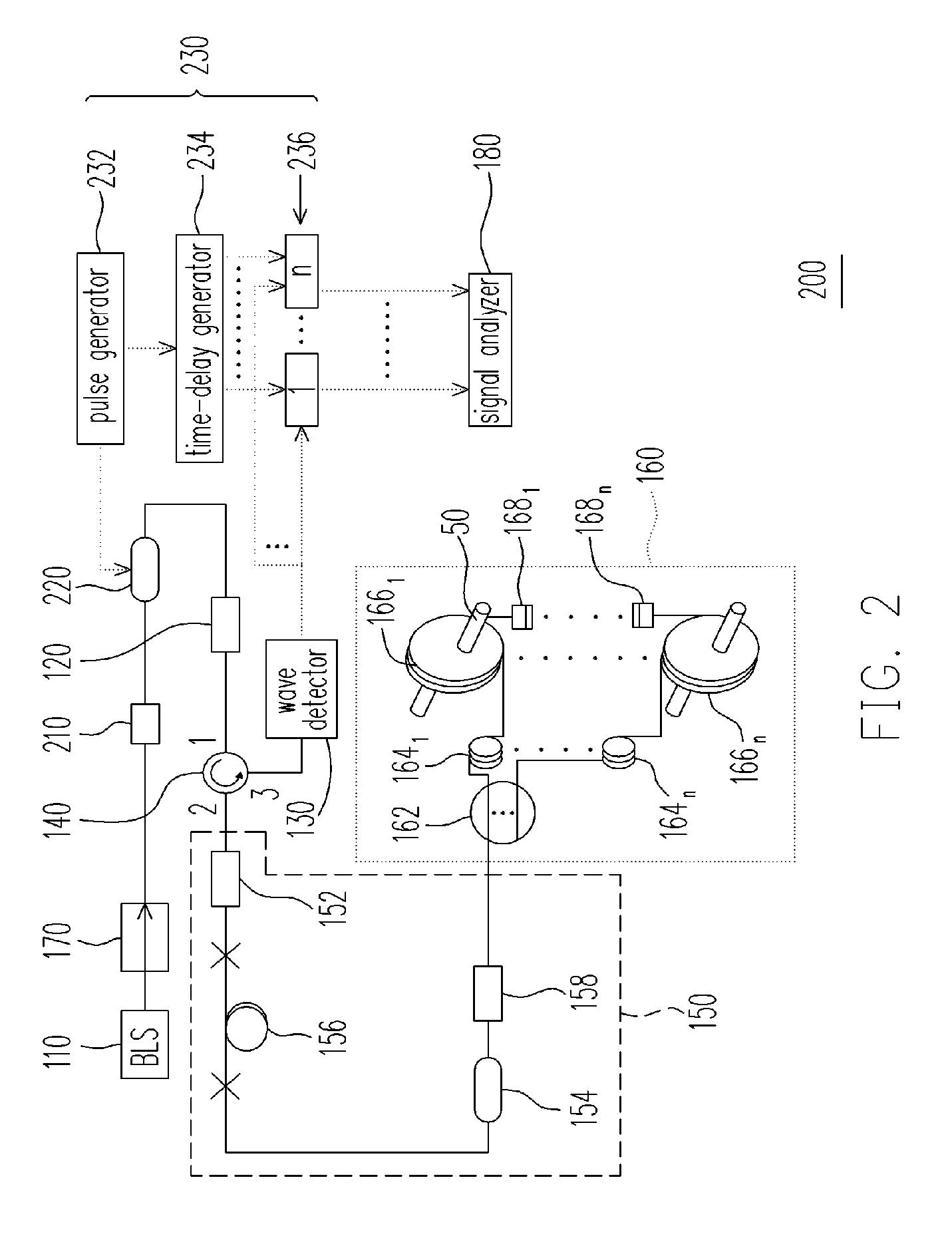
[0037]FIG. 2 is a schematic structural diagram of a fiber-optics multiplexed interferometric current sensor according to the second embodiment of the invention. Referring to FIG. 2, the fiber-optics multiplexed interferometric current sensor 200 according to the second embodiment of the invention is adapted for simultaneously sensing currents of the same frequency loaded by a plurality of wires 50. The fiber-optics multiplexed interferometric current sensor 200 is similar with the fiber-optics multiplexed interferometric current sensor 100 of the first embodiment, in which those elements labeled with the same numbers of FIG. 1 function as same as the first embodiment and will not be repeated herein.
[0038] Comparing with the first embodiment, the fiber-optics multiplexed interferometric current sensor 200 according to the second embodiment further includes a polarizer 210, an optical modulator 220 and a time-division multiplexing (TDM) circuit 230. The optical m...
third embodiment
The Third Embodiment
[0041]FIG. 3A is a schematic structural diagram of a fiber-optics multiplexed interferometric current sensor 300 according to the third embodiment of the invention. FIG. 3B is a schematic structural diagram illustrating passive demodulating interferometric modules and sensor modules according to the third embodiment as illustrated in FIG. 3A. Referring to FIGS. 3A and 3B, the fiber-optics multiplexed interferometric current sensor 300 is similar with the fiber-optics multiplexed interferometric current sensor 100 of the first embodiment, in which those elements labeled with the same numbers of FIG. 1 function as same as the first embodiment and will not be repeated herein.
[0042] The fiber-optics multiplexed interferometric current sensor 300 according to the third embodiment of the invention includes a BLS 110, a depolarizer 120, a 1×n optical coupler 162, a plurality of optical spliters 1401 through 140n, a plurality of wave detectors 1301 through 130n, a plura...
PUM
 Abstract
Description
Claims
Application Information
 - R&D Engineer
- R&D Manager
- IP Professional
- Industry Leading Data Capabilities
- Powerful AI technology
- Patent DNA Extraction
Browse by: Latest US Patents, China's latest patents, Technical Efficacy Thesaurus, Application Domain, Technology Topic.
© 2024 PatSnap. All rights reserved.Legal|Privacy policy|Modern Slavery Act Transparency Statement|Sitemap