Eureka AIR delivers breakthrough ideas for toughest innovation challenges, trusted by R&D personnel around the world.

Inert processing of oxide ceramic matrix composites and oxidation sensitive ceramic materials and intermediate structures and articles incorporating same

Inactive Publication Date: 2007-03-22
COI CERAMICS
View PDF5 Cites 9 Cited by
  • Summary
  • Abstract
  • Description
  • Claims
  • Application Information

AI Technical Summary

Benefits of technology

[0008] The co-cured, structurally integrated precursor component is then co-fired in an inert environment by exposing the co-cured, structurally integrated precursor component to a temperature sufficient to bond the first ceramic material and the second ceramic material, such as a temperature ranging from approximately 900° C. to approximately 1200° C. The co-cured, structurally integrated precursor component may b

Problems solved by technology

However, the ceramic adhesive potentially limits the size and configuration of the complex ceramic structure that is capable of being produced and also potentially limits the temperature at which the complex ceramic structure is able to be used.
In addition, the strength of the joint between the dissimilar ceramic materials is typically low.
However, with mold

Method used

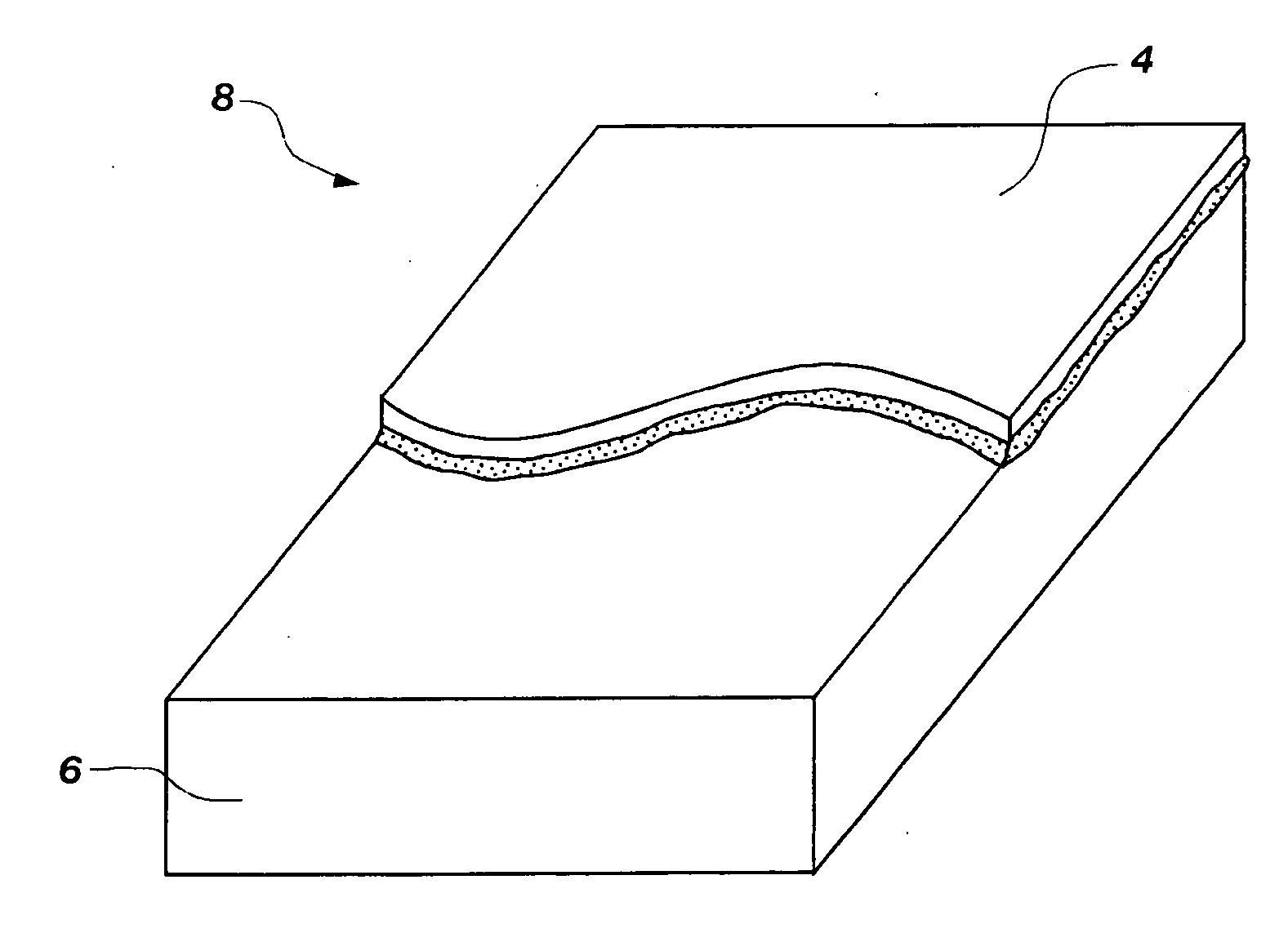
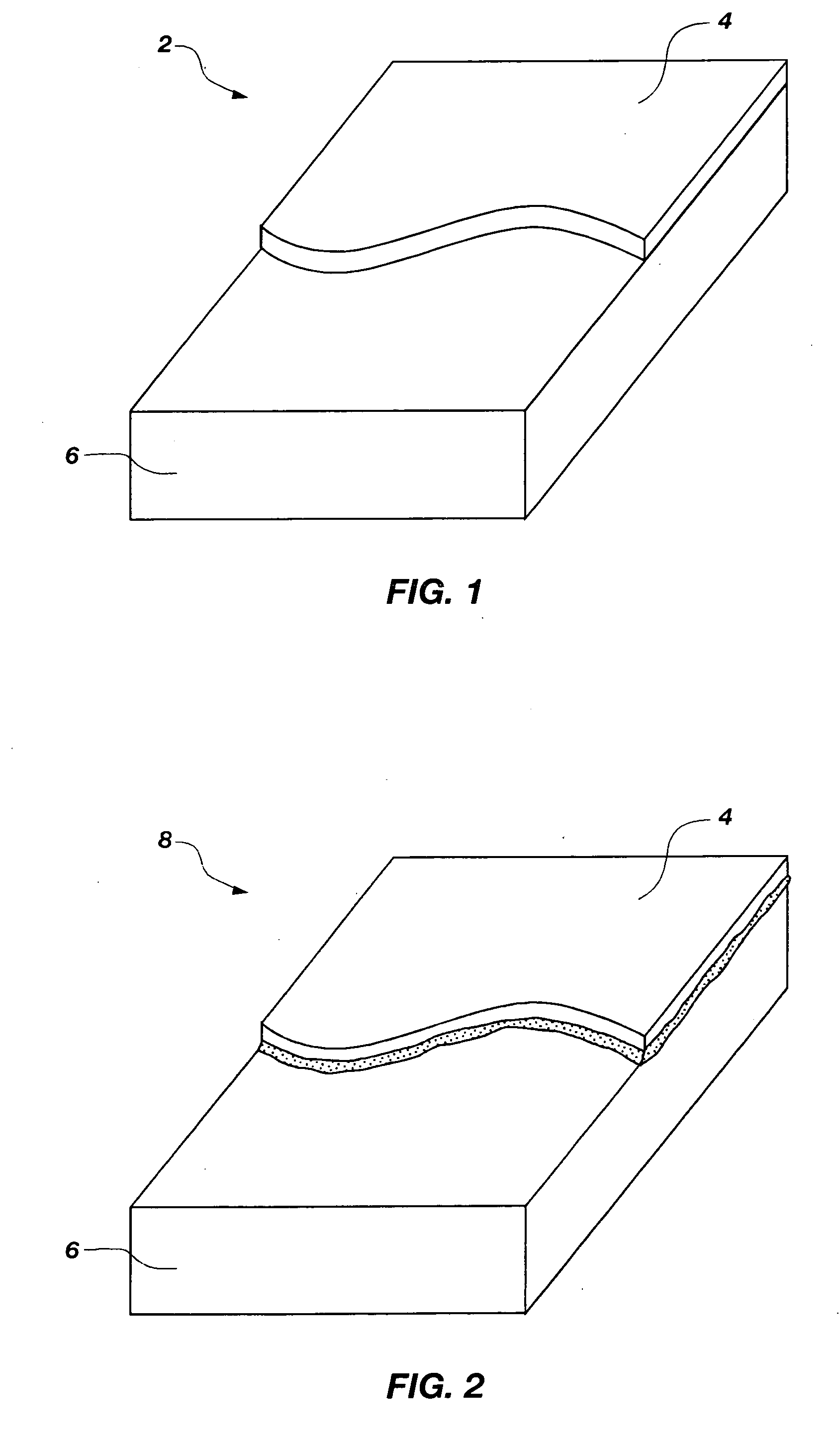

Image

  • Inert processing of oxide ceramic matrix composites and oxidation sensitive ceramic materials and intermediate structures and articles incorporating same
  • Inert processing of oxide ceramic matrix composites and oxidation sensitive ceramic materials and intermediate structures and articles incorporating same
  • Inert processing of oxide ceramic matrix composites and oxidation sensitive ceramic materials and intermediate structures and articles incorporating same

Examples


example 1

Curing of a Laminate Formed from AS / N312HT-1

[0034] A prepreg formed from AS / N312HT-1 (available from COI Ceramics, Inc.) was laid-up to form a laminate. The prepreg was four square feet in size and was prepared from fresh slurry according to the manufacturer's directions. The laminate of the prepreg was cut into nine, 4″×4″ stacks. To cure the AS / N312HT-1 prepreg, the laminate was placed in an autoclave. Nitrogen was flowed into the autoclave at an inlet pressure of 10 psi and an inlet flow rate of 10 cubic feet per hour at standard conditions (“SCFH”). A pressure of approximately 60 PSI was applied to the autoclave. The temperature in the autoclave was ramped from approximately 75° C. to approximately 200° C. at a maximum of 0.04° C. / minute. The temperature was maintained at approximately 200° C. for approximately 12 hours to cure the laminate. The cured laminate was removed from the autoclave and allowed to cool to room temperature.

example 2

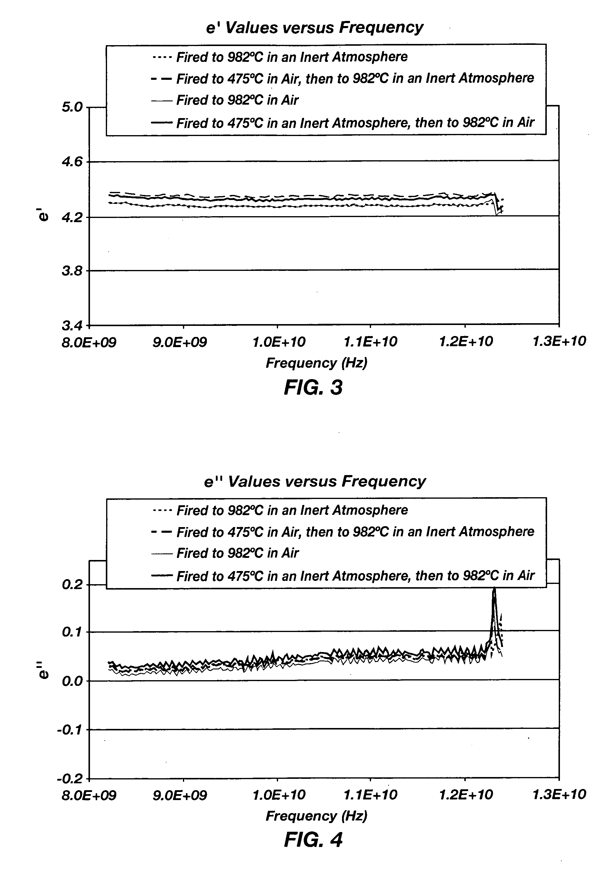
Firing of the Cured Laminate Using an Inert Firing Cycle

[0035] One of the pieces of the laminate (#1) was placed in an inert atmosphere furnace for firing. The inert atmosphere furnace was evacuated until the rate of pressure decrease slowed. When a pressure of 175 mTorr was achieved, the inert atmosphere furnace was purged with nitrogen. The evacuation and nitrogen purge were repeated. The temperature in the inert atmosphere furnace was increased to 982° C. The temperature was maintained for approximately 3 hours and then the temperature in the inert atmosphere furnace was decreased to approximately 200° C. After the inert atmosphere furnace automatically evacuated and purged twice, the laminate was cooled to room temperature in the inert atmosphere furnace.

example 3

Firing of the Cured Laminate Using a Modified Ambient / Inert Firing Cycle

[0036] One of the pieces of the laminate (#2) was placed in an ambient atmosphere furnace for firing. The temperature in the ambient atmosphere furnace was increased to approximately 475° C. The laminate was then placed in an inert atmosphere furnace, which was evacuated. When a pressure of 175 mTorr was achieved, the inert atmosphere furnace was purged with nitrogen. The evacuation and nitrogen purge were repeated. The temperature in the inert atmosphere furnace was increased to approximately 982° C. The temperature was maintained for approximately 3 hours and then the temperature in the inert atmosphere furnace was decreased to approximately 200° C. The laminate was removed from the inert atmosphere furnace and allowed to cool to room temperature.


PUM

PropertyMeasurementUnit
Temperatureaaaaaaaaaa

Abstract

A method of forming a structurally integrated component. The method comprises providing a first ceramic material comprising an oxidation sensitive ceramic material and providing a second ceramic material comprising an uncured, oxide ceramic matrix composite. The first ceramic material may be a carbon-based ceramic material selected from the group consisting of carbon fibers, carbon whiskers, carbon powder, graphite, silicon carbide, silicon oxycarbide, and mixtures thereof. The second ceramic material may comprise an inorganic oxide fiber reinforcement impregnated with an alumina matrix or an aluminosilicate matrix. The second ceramic material and the first ceramic material are contacted to form an uncured, structurally integrated precursor component, which is co-cured. The co-cured, structurally integrated precursor component is then co-fired in an inert atmosphere to bond the first ceramic material and the second ceramic material. A co-cured, structurally integrated precursor component and a structurally integrated component are also disclosed.

Description

STATEMENT REGARDING FEDERALLY SPONSORED RESEARCH [0001] The United States Government has a paid-up license in this invention and the right in limited circumstances to require the patent owner to license others on reasonable terms as provided for by the terms of Contract No. DAAH23-00-C-A001 awarded by the Department of Defense.FIELD OF THE INVENTION [0002] The present invention relates to a method of joining dissimilar ceramic materials without affecting desirable properties of the ceramic materials. More specifically, the present invention relates to joining an oxide ceramic matrix composite (“CMC”) and an oxidation sensitive ceramic material. BACKGROUND OF THE INVENTION [0003] Ceramic materials are known to have good hardness and resistance to heat, abrasion, and corrosion. Therefore, ceramic materials are commonly used in high temperature environments, such as in high speed cutting and grinding tools, furnace heating elements and igniters, or thermal barrier coatings for metals. ...

Claims


Application Information

Patent Timeline
IPC IPC(8): B28B3/00B32B19/00B28B1/00
CPCB32B18/00C04B35/6269C04B37/001C04B2235/77C04B2237/341C04B2235/658C04B2237/363C04B2237/38C04B2237/704C04B2235/6567C04B2237/343
Inventor BACALSKI, CARLOS F.FISCHER, BELINDA A.PLUNKETT, RICHARD
Owner COI CERAMICS
Why Eureka
Eureka Blog
Learn More