Wear resistant ceramic composite coatings and process for production thereof

A technology of ceramic coatings and ceramics, which is applied in coatings, metal material coating processes, air transportation, etc., and can solve problems such as parts that cannot withstand high temperatures, limitations, and labor

Inactive Publication Date: 2008-08-20
STANDARD AERO SAN ANTONIO
View PDF0 Cites 24 Cited by
  • Summary
  • Abstract
  • Description
  • Claims
  • Application Information

AI Technical Summary

Problems solved by technology

However, the use of this slurry method is also limited because some components cannot withstand the high temperatures required
Also, thicker coatings cannot be applied using slurries unless a laborious, expensive, multi-step process is used

Method used


Image

  • Wear resistant ceramic composite coatings and process for production thereof
  • Wear resistant ceramic composite coatings and process for production thereof

Examples


Embodiment 1

[0035] Embodiment 1 (comparative example)

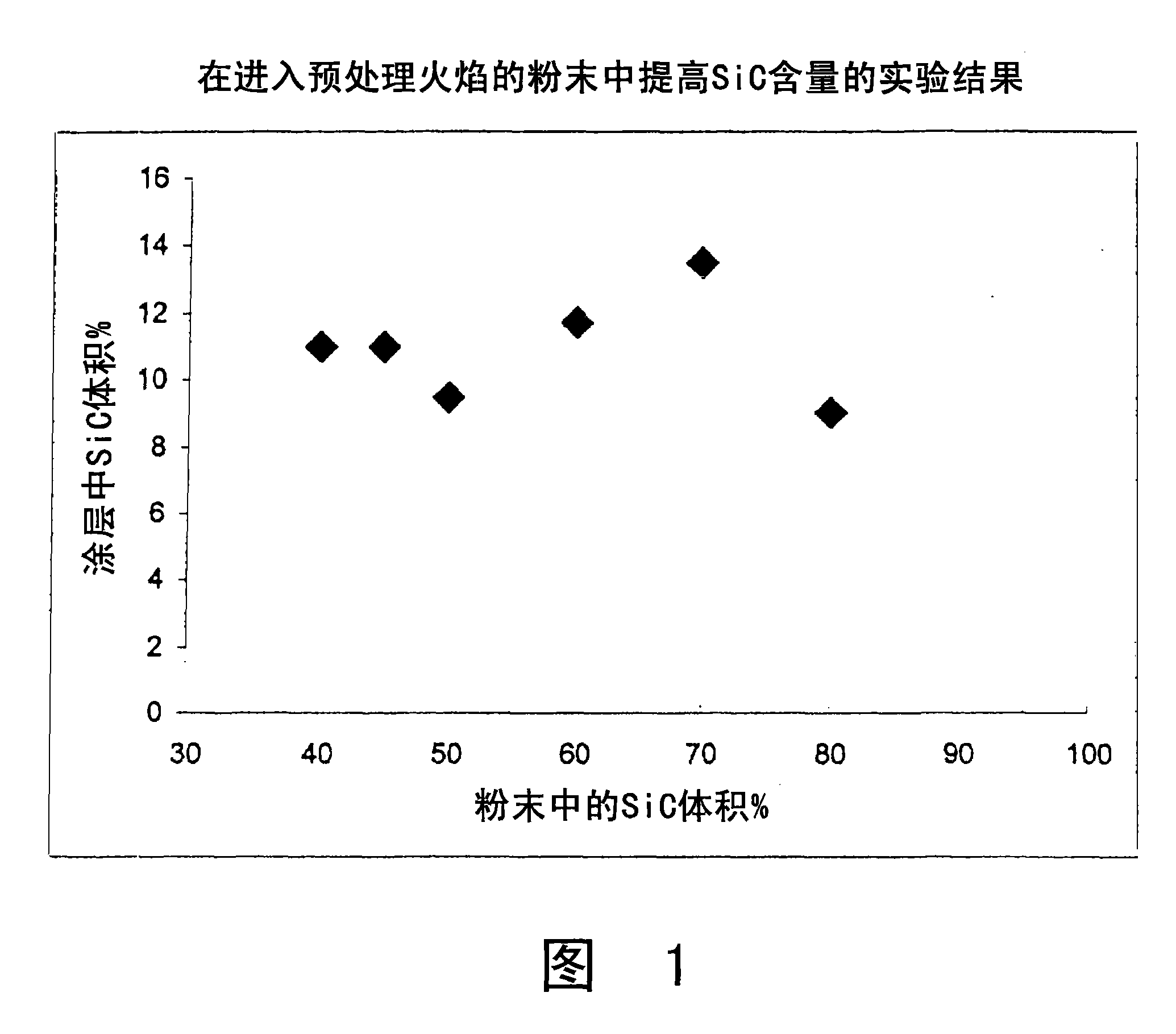
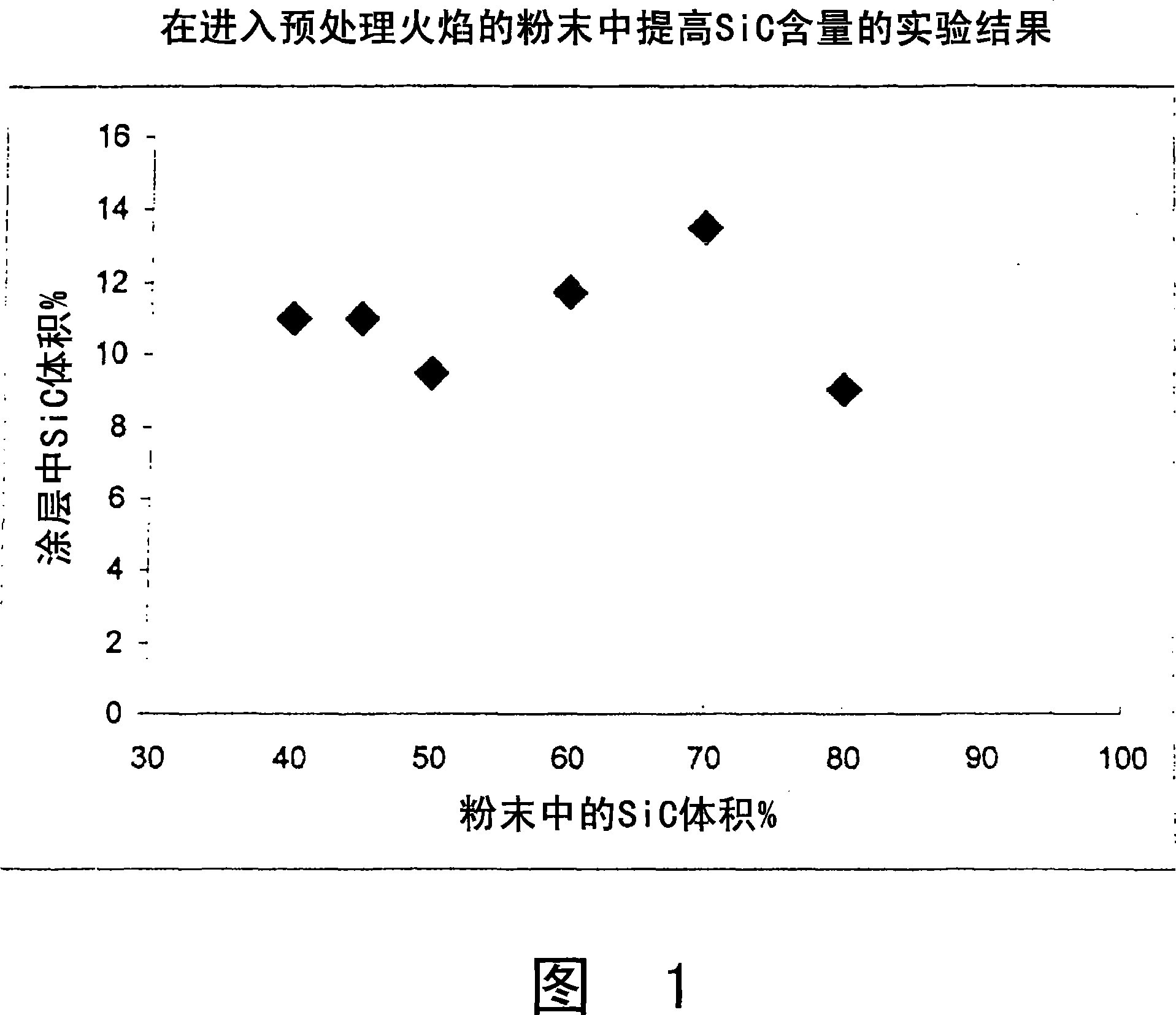
[0036] In this example, silicon carbide is selected as the carbide, with a size less than 70 microns, stored in the first silo. Alumina is selected as the oxide, with a size less than 75 microns and stored in a second silo. Carbides and oxides were co-injected into the APS torch from two separate silos and deposited on the grit-blasted stainless steel substrate. Provided that the procedure is repeated several times until a coating with an apparent thickness of 250 microns is obtained. The purpose of the test was to demonstrate whether a high SiC content in the coating could be obtained without first pretreating the SiC.

[0037] Several sets of tests were performed with different powder feed rates to vary the silicon carbide fraction in the APS torch flame. The silicon carbide volume percent in the plasma torch was varied between 40, 45, 50, 60, 70 and 80 volume percent, the remaining component in the torch in each set of tests be...

Embodiment 2

[0042] In this example, an aqueous slurry containing 98.5% by weight silicon carbide was prepared containing 80 milliliters of water per 100 grams of silicon carbide powder smaller than 70 microns (220 mesh). During pretreatment, the slurry is mixed with submicron sized cobalt and aluminum oxides. After wet mixing for 30 minutes and drying at 149°C (300°F) for 1.5 hours, the dried mixture was tumbled to remove lumps. The prepared ceramic raw material stock was then co-injected into the APS welding torch with alumina (200 mesh screen) smaller than 75 microns and deposited on the grit blasted stainless steel substrate. The volume fraction of silicon carbide treated in the flame was 70% by volume. Provided that the procedure was repeated several times until a coating with an apparent thickness of 250 microns was obtained. Measurements of the coating showed a silicon carbide concentration of 38% and a porosity of less than 5% by volume.

Embodiment 3

[0044] In this example, silicon carbide powder of less than 45 microns was dry blended with 0.05 micron alumina in a tumbler, the mixture containing 70% by weight silicon carbide. After 90 minutes of tumble mixing, the resulting ceramic powder mixture (preparation) was co-injected into an APS torch with alumina < 75 microns and deposited on a grit-blasted stainless steel substrate. The volume fraction of silicon carbide treated in the flame was 40% by volume. Provided that the procedure was repeated several times until a coating with an apparent thickness of 250 microns was obtained. Measurements of the coating showed a silicon carbide concentration of 67% and a porosity of less than 5% by volume.


PUM

PropertyMeasurementUnit
particle diameteraaaaaaaaaa
thicknessaaaaaaaaaa

Abstract

A binder-free ceramic feedstock composition for thermal spraying on a surface of an article is provided. The composition comprises: an oxide ceramic powder and a boride and / or carbide ceramic powder. The boride and / or carbide ceramic powders are comprised of micron-sized particles, and the volume content of the oxide ceramic powder is in the range of about 1 to about 85 percent. A method for preparing the binder-free ceramic feedstock and a coated article by a thermal spraying process are also provided.

Description

field of invention [0001] The present invention relates to a ceramic composite for surface application of a target material, and a method for preparing the ceramic composite. Background of the invention [0002] Protective surface coatings often have properties that include extremely high hardness and wear-resistant properties. Ceramics are attractive candidates for such coatings. Unfortunately, pure ceramics cannot be widely used in coatings due to the poor mechanical bonding generally observed when ceramics are applied to surfaces. [0003] Existing efforts to increase the cohesive and adhesive strength of ceramics have shown that these particles must be softened or melted before being used in coatings. Without this pretreatment, ceramics may not bond or may easily peel off surfaces like paved or blasted targets. [0004] The desired softening, or in some cases melting, is typically achieved by preheating the ceramic at elevated temperatures until the softening temperat...

Claims


Application Information

Patent Timeline
Patent Type & Authority Applications(China)
IPC IPC(8): C09D1/00C04B35/56C04B35/04C04B35/58C23C4/11
CPCC04B35/117C04B35/58071C04B2235/3217C04B2235/3813C04B2235/3826C09D1/00C23C4/10C04B35/565C04B2235/3275C04B2235/5436C04B2235/5445C04B2235/5472C04B35/04Y02T50/60
Inventor K·山卡A·G·克莱杰
Owner STANDARD AERO SAN ANTONIO
Why Eureka
Try Eureka